How to Use Adafruit 1.2 Inch 8x8 LED Matrix Backpack Red: Examples, Pinouts, and Specs
Introduction
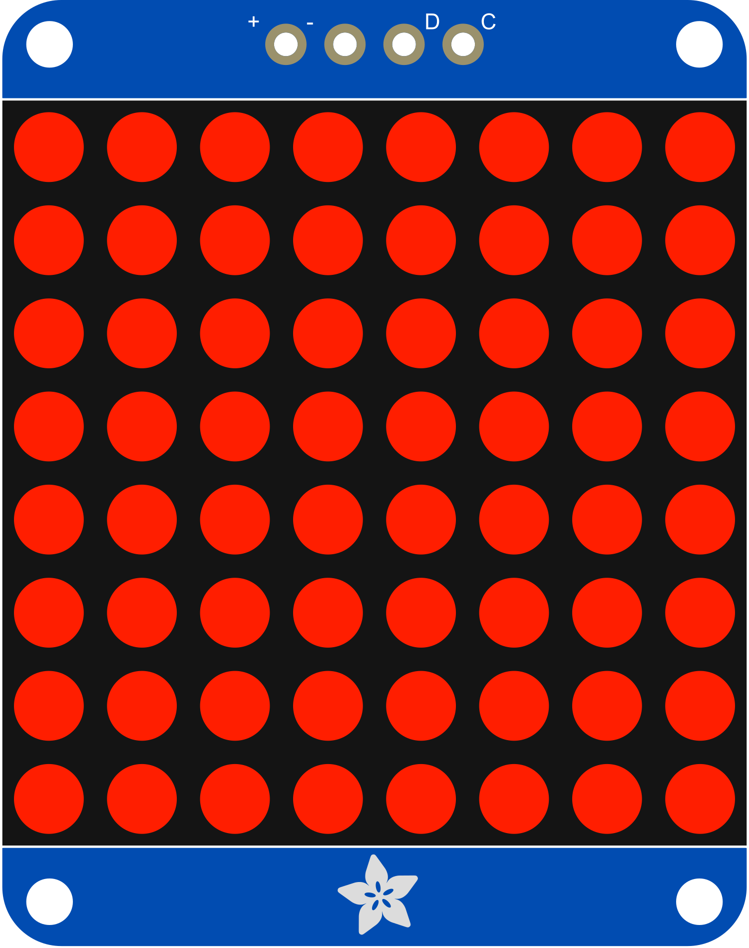
The Adafruit 1.2 Inch 8x8 LED Matrix Backpack Red is a compact and versatile electronic component that simplifies the process of controlling an 8x8 LED matrix. This driver board is designed to work seamlessly with red LEDs, providing a bright and clear display for a variety of applications. Common uses include creating digital signage, gaming displays, and adding visual output to various electronic projects.
Explore Projects Built with Adafruit 1.2 Inch 8x8 LED Matrix Backpack Red

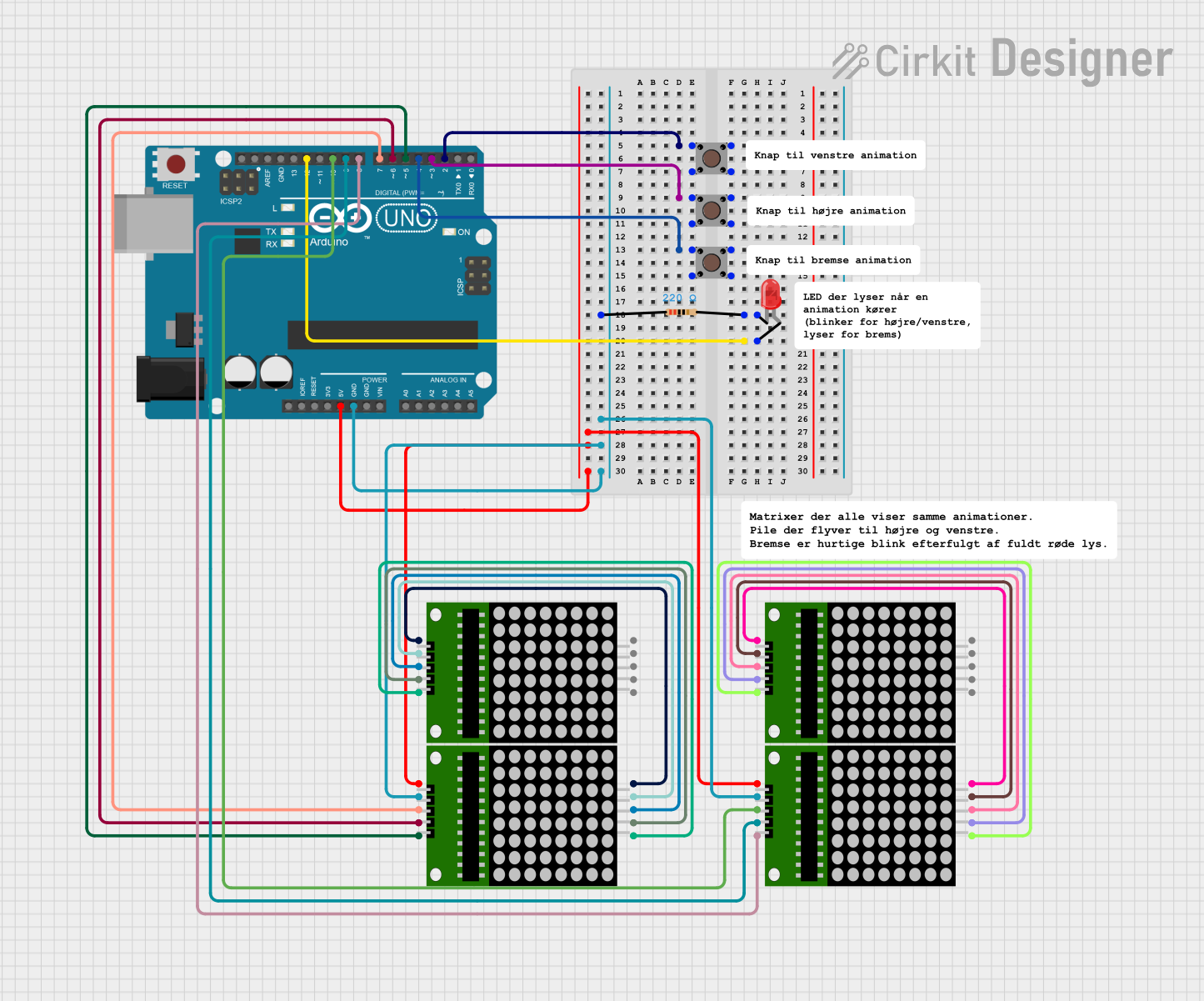

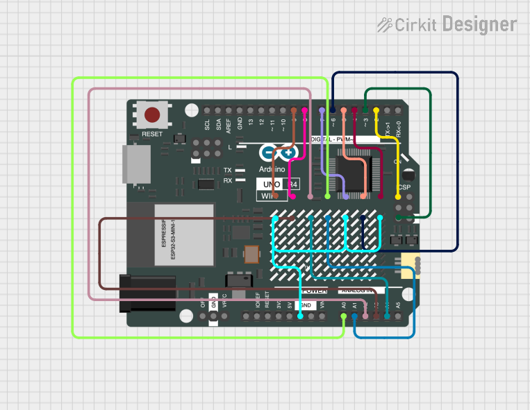
Explore Projects Built with Adafruit 1.2 Inch 8x8 LED Matrix Backpack Red
Technical Specifications
Key Technical Details
- Display Color: Red
- Matrix Dimensions: 1.2 inches (8x8 grid)
- Operating Voltage: 4.5V - 5.5V
- Max Current (per LED): 30 mA
- Max Current (for all LEDs): 500 mA
- Communication: I2C interface
- I2C Addresses: 0x70 (default) - 0x77 (selectable with solder jumpers)
Pin Configuration and Descriptions
| Pin Number | Name | Description |
|---|---|---|
| 1 | GND | Ground connection |
| 2 | VCC | Power supply (4.5V - 5.5V) |
| 3 | SDA | I2C Data line |
| 4 | SCL | I2C Clock line |
Usage Instructions
Integrating with a Circuit
To use the Adafruit 1.2 Inch 8x8 LED Matrix Backpack Red in a circuit, follow these steps:
- Connect the GND pin to the ground of your power supply.
- Connect the VCC pin to a 4.5V - 5.5V power supply.
- Connect the SDA and SCL pins to the I2C data and clock lines of your microcontroller (e.g., Arduino UNO).
Important Considerations and Best Practices
- Ensure that the power supply does not exceed 5.5V to prevent damage to the LED matrix.
- When multiple LED matrix backpacks are used, make sure to set unique I2C addresses for each by adjusting the solder jumpers.
- To avoid excessive power draw, do not illuminate all LEDs at maximum brightness simultaneously for extended periods.
Example Code for Arduino UNO
#include <Wire.h>
#include <Adafruit_GFX.h>
#include <Adafruit_LEDBackpack.h>

Adafruit_8x8matrix matrix = Adafruit_8x8matrix();

void setup() {
  matrix.begin(0x70); // Start the LED matrix with the default I2C address
  Wire.begin();       // Join the I2C bus as a master
}

void loop() {
  matrix.clear();      // Clear the matrix display
  matrix.drawPixel(0, 0, LED_ON); // Turn on a single LED at the top-left corner
  matrix.writeDisplay();  // Write the changes to the display
  delay(500);            // Wait for half a second
  matrix.clear();        // Clear the display again
  matrix.writeDisplay(); // Update the display
  delay(500);            // Wait for another half a second
}
Troubleshooting and FAQs
Common Issues
- LEDs Not Lighting Up: Ensure that the power supply is correctly connected and within the specified voltage range. Check the I2C connections and verify that the correct I2C address is being used in your code.
- Dim LEDs: If the LEDs are dim, the power supply may be insufficient, or the brightness setting in the code may be too low.
- Flickering Display: Flickering can occur if there is a loose connection or if the refresh rate in the code is set too high.
Solutions and Tips
- Double-check all connections, especially the I2C lines, for solid contact.
- Use a multimeter to verify the voltage at the VCC pin.
- Ensure that the Adafruit LED Backpack library is correctly installed in your Arduino IDE.
FAQs
Q: Can I daisy-chain multiple LED matrix backpacks? A: Yes, you can connect multiple backpacks in series via the I2C bus. Remember to set a unique I2C address for each backpack.
Q: How do I change the brightness of the LEDs?
A: You can adjust the brightness in your code using the setBrightness() function provided by the Adafruit LED Backpack library.
Q: What is the maximum number of LED matrix backpacks I can control with a single microcontroller? A: You can control up to 8 LED matrix backpacks on a single I2C bus, as there are 8 available I2C addresses from 0x70 to 0x77.