How to Use Gravity: MOSFET Power Controller: Examples, Pinouts, and Specs
Introduction
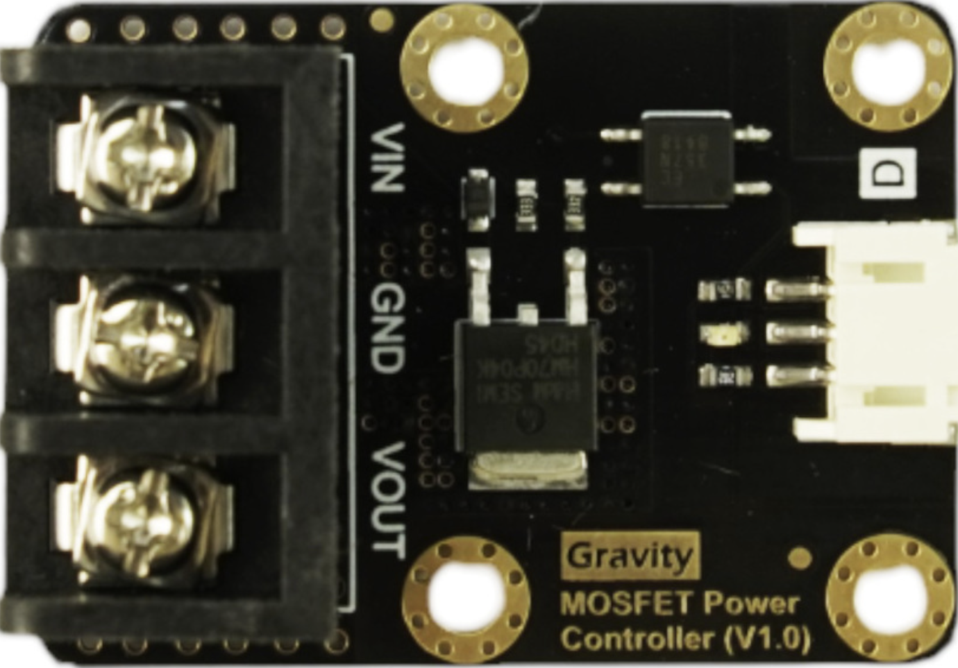
The Gravity: MOSFET Power Controller (Manufacturer Part ID: DFR0457) by DFROBOT is a versatile and efficient power management module designed for controlling high-power loads in electronic circuits. It leverages the capabilities of MOSFETs (Metal-Oxide-Semiconductor Field-Effect Transistors) to provide high-speed switching, low power loss, and reliable operation. This module is ideal for applications requiring precise power control, such as motor drivers, LED lighting systems, and heating elements.
Explore Projects Built with Gravity: MOSFET Power Controller


Explore Projects Built with Gravity: MOSFET Power Controller
Common Applications and Use Cases
- Driving high-power LEDs or lighting systems
- Controlling DC motors or actuators
- Power management in IoT devices
- Switching high-current loads in automation systems
- Heating element control in temperature regulation systems
Technical Specifications
The following table outlines the key technical details of the Gravity: MOSFET Power Controller:
| Parameter | Specification |
|---|---|
| Operating Voltage | 3.3V to 20V |
| Maximum Load Current | 30A (with proper heat dissipation) |
| Control Signal Voltage | 3.3V or 5V (logic level compatible) |
| MOSFET Type | N-Channel |
| On-Resistance (RDS(on)) | ≤ 10mΩ |
| Switching Frequency | Up to 20kHz |
| Dimensions | 32mm x 22mm |
| Weight | 10g |
Pin Configuration and Descriptions
The module features a simple pinout for easy integration into your projects:
| Pin Name | Type | Description |
|---|---|---|
| VIN | Power Input | Connect to the positive terminal of the power source. |
| VOUT | Power Output | Connect to the positive terminal of the load. |
| GND | Ground | Common ground for the power source and load. |
| SIG | Signal Input | Control signal input (3.3V or 5V logic level). |
Usage Instructions
How to Use the Component in a Circuit
Power Connections:
- Connect the VIN pin to the positive terminal of your power source (e.g., battery or power supply).
- Connect the GND pin to the ground terminal of your power source and load.
- Connect the VOUT pin to the positive terminal of your load (e.g., motor, LED, or heating element).
Control Signal:
- Use a microcontroller (e.g., Arduino UNO) or other logic-level device to send a control signal to the SIG pin.
- A HIGH signal (3.3V or 5V) will turn the MOSFET ON, allowing current to flow through the load.
- A LOW signal will turn the MOSFET OFF, cutting off current to the load.
Heat Dissipation:
- For high-current applications, ensure proper heat dissipation by attaching a heatsink to the MOSFET or using active cooling.
Important Considerations and Best Practices
- Voltage Compatibility: Ensure the input voltage (VIN) is within the module's operating range (3.3V to 20V).
- Current Handling: Do not exceed the maximum load current of 30A. Use proper heat dissipation for high-current loads.
- Signal Voltage: The control signal should be 3.3V or 5V logic level. Avoid applying higher voltages to the SIG pin.
- Switching Frequency: For applications requiring high-speed switching, ensure the control signal frequency does not exceed 20kHz.
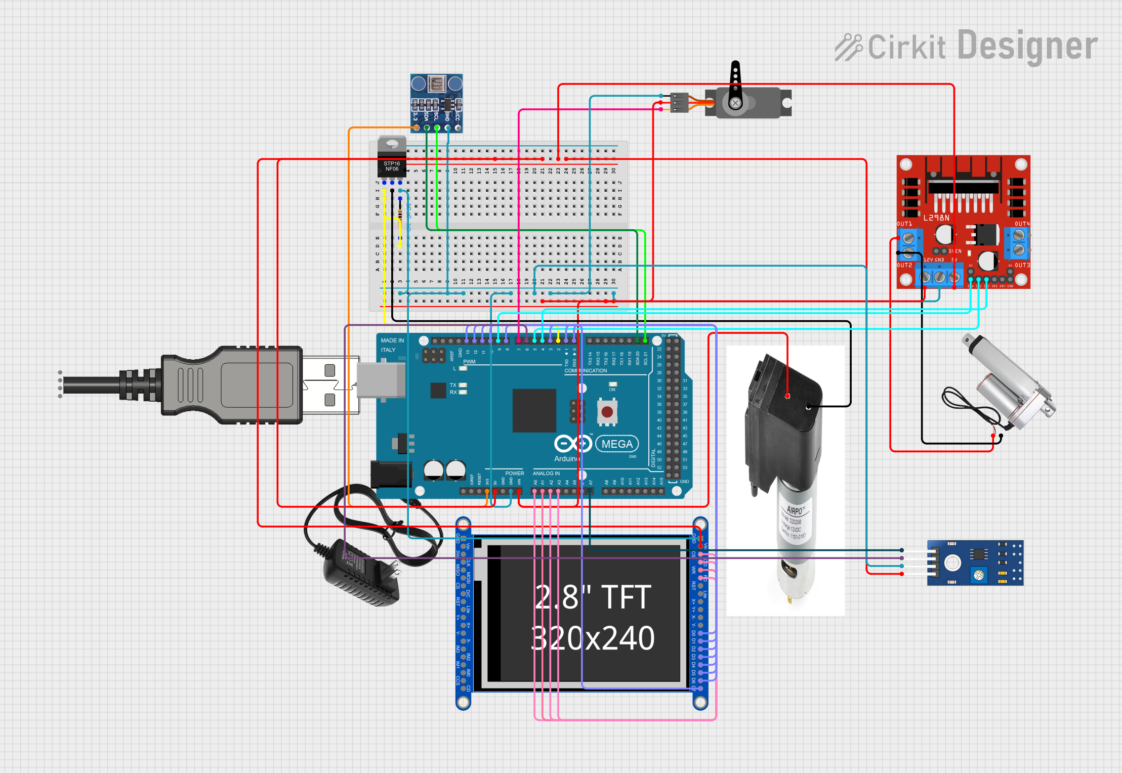
Example: Using with Arduino UNO
Below is an example of how to control the Gravity: MOSFET Power Controller using an Arduino UNO to drive a 12V LED strip.
Circuit Diagram
- Connect the VIN pin to a 12V power supply.
- Connect the VOUT pin to the positive terminal of the LED strip.
- Connect the GND pin to the ground of the power supply and Arduino.
- Connect the SIG pin to a PWM-capable pin on the Arduino (e.g., Pin 9).
Arduino Code
// Define the control pin for the MOSFET Power Controller
const int mosfetControlPin = 9;

void setup() {
  // Set the MOSFET control pin as an output
  pinMode(mosfetControlPin, OUTPUT);
}

void loop() {
  // Gradually increase brightness (PWM duty cycle)
  for (int brightness = 0; brightness <= 255; brightness++) {
    analogWrite(mosfetControlPin, brightness); // Send PWM signal
    delay(10); // Small delay for smooth transition
  }

  // Gradually decrease brightness
  for (int brightness = 255; brightness >= 0; brightness--) {
    analogWrite(mosfetControlPin, brightness); // Send PWM signal
    delay(10); // Small delay for smooth transition
  }
}
Troubleshooting and FAQs
Common Issues and Solutions
The load does not turn ON:
- Ensure the power source is connected and providing the correct voltage.
- Verify that the control signal (SIG pin) is HIGH (3.3V or 5V).
- Check all connections for loose wires or poor solder joints.
The MOSFET overheats:
- Ensure the load current does not exceed 30A.
- Attach a heatsink or use active cooling for high-power applications.
The module does not respond to the control signal:
- Confirm that the control signal voltage is within the acceptable range (3.3V or 5V).
- Check the Arduino code or microcontroller configuration for errors.
PWM control is not smooth:
- Ensure the control signal frequency does not exceed 20kHz.
- Verify that the load is compatible with PWM control.
FAQs
Q: Can I use this module with a 24V power source?
A: No, the maximum input voltage for this module is 20V. Using a 24V power source may damage the module.
Q: Is the module compatible with 3.3V microcontrollers like the ESP32?
A: Yes, the SIG pin is compatible with both 3.3V and 5V logic levels.
Q: Can I use this module to control an AC load?
A: No, this module is designed for DC loads only. Do not use it with AC loads.
Q: What is the maximum switching frequency?
A: The module supports switching frequencies up to 20kHz.