How to Use PID Temperature Controller: Examples, Pinouts, and Specs
Introduction
The Auber Instruments SYL-2362A2 is a PID (Proportional-Integral-Derivative) Temperature Controller designed for precise temperature regulation in a variety of applications. It uses advanced PID algorithms to maintain a desired temperature by controlling heating or cooling elements based on feedback from temperature sensors. This controller is widely used in industrial, laboratory, and DIY projects where accurate temperature control is critical.
Explore Projects Built with PID Temperature Controller

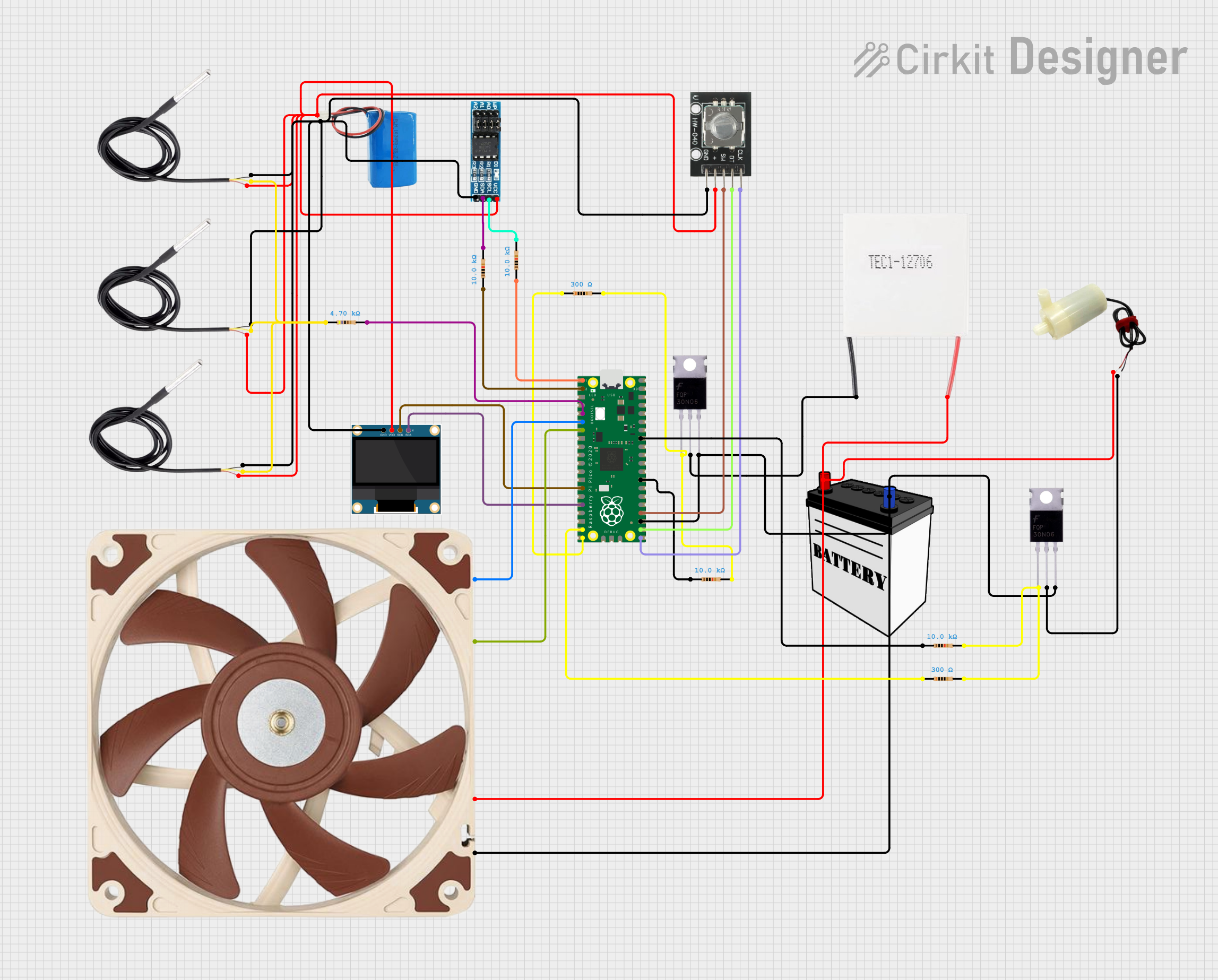
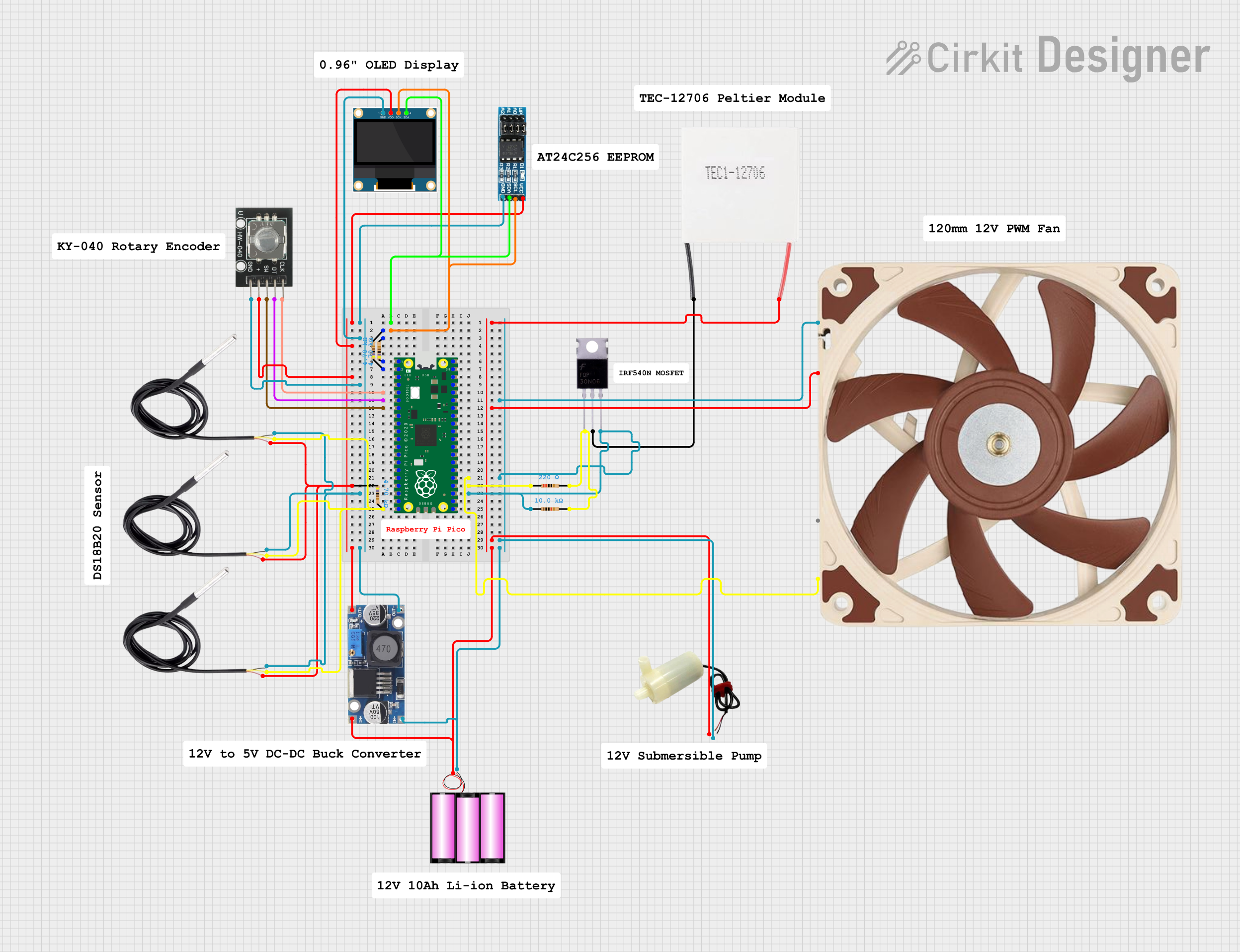
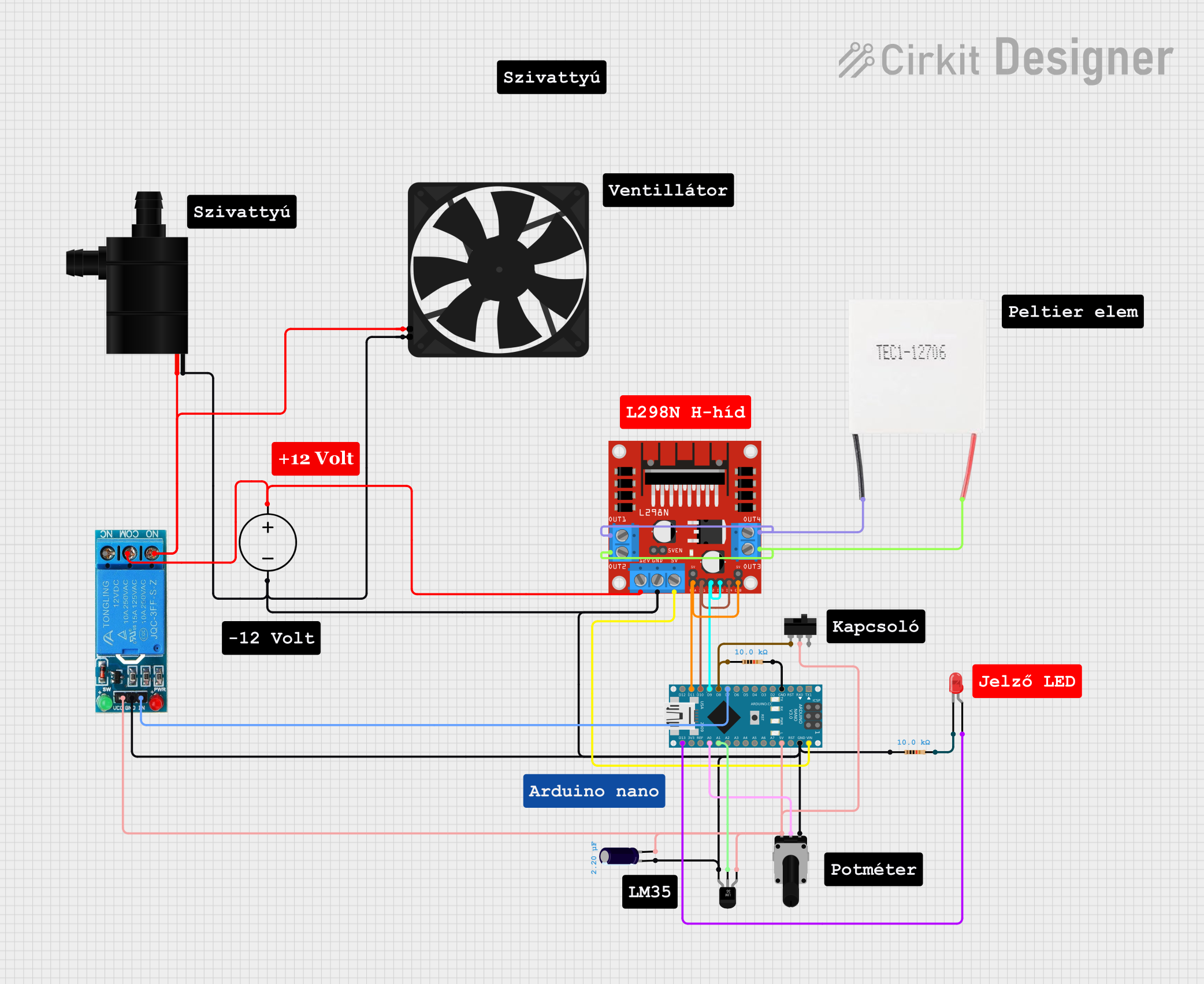
Explore Projects Built with PID Temperature Controller
Common Applications and Use Cases
- Industrial ovens and furnaces
- Brewing and distillation systems
- Sous-vide cooking
- Incubators and environmental chambers
- 3D printer heated beds
- Scientific experiments requiring precise thermal control
Technical Specifications
The following table outlines the key technical details of the SYL-2362A2 PID Temperature Controller:
| Parameter | Specification |
|---|---|
| Input Voltage | 85-264 VAC, 50/60 Hz |
| Output Type | Relay, SSR (Solid State Relay) |
| Temperature Sensor Input | Thermocouple (K, J, T, E, N, S, R, B) or RTD (Pt100) |
| Temperature Range | -199°C to 1800°C (sensor-dependent) |
| Control Mode | PID, ON/OFF |
| Display Type | Dual 4-digit LED display |
| Accuracy | ±0.2% of full scale |
| Dimensions | 48 x 48 x 110 mm |
| Operating Temperature | 0°C to 50°C |
| Weight | 200 g |
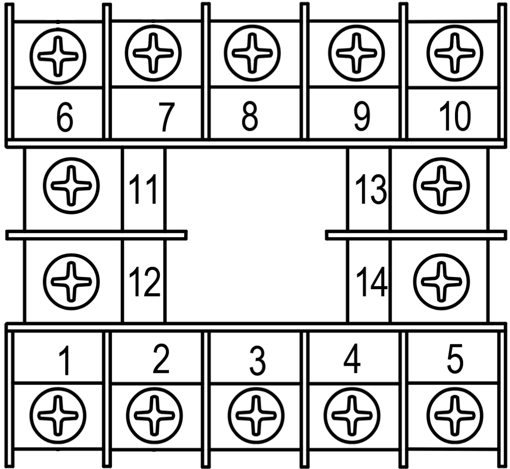
Pin Configuration and Descriptions
The SYL-2362A2 has a terminal block for wiring connections. Below is the pin configuration:
| Pin Number | Label | Description |
|---|---|---|
| 1 | AC (L) | Live input for AC power |
| 2 | AC (N) | Neutral input for AC power |
| 3 | Sensor Input + | Positive terminal for temperature sensor |
| 4 | Sensor Input - | Negative terminal for temperature sensor |
| 5 | Relay Output 1 | Relay output for heating or cooling control |
| 6 | Relay Output 2 | Optional second relay output (if configured) |
| 7 | SSR Output + | Positive terminal for Solid State Relay control |
| 8 | SSR Output - | Negative terminal for Solid State Relay control |
Usage Instructions
How to Use the Component in a Circuit
- Power Connection: Connect the AC power supply to pins 1 (Live) and 2 (Neutral). Ensure the voltage matches the input voltage specification (85-264 VAC).
- Sensor Connection: Attach the temperature sensor (e.g., K-type thermocouple or Pt100 RTD) to pins 3 and 4. Ensure proper polarity for accurate readings.
- Output Connection:
- For relay control, connect the heating or cooling element to pins 5 and 6.
- For SSR control, connect the SSR input terminals to pins 7 and 8.
- Set the Parameters:
- Use the front panel buttons to configure the setpoint temperature, PID parameters, and control mode (PID or ON/OFF).
- Refer to the user manual for detailed instructions on parameter settings.
- Start Operation: Once all connections are secure and parameters are set, power on the controller. The device will begin regulating the temperature based on the configured settings.
Important Considerations and Best Practices
- Sensor Compatibility: Ensure the temperature sensor type matches the controller's input configuration.
- PID Tuning: Properly tune the PID parameters (Proportional, Integral, Derivative) for optimal performance. Use the auto-tuning feature if available.
- Load Ratings: Verify that the connected heating or cooling element does not exceed the controller's output current or voltage ratings.
- Safety Precautions: Always disconnect power before wiring or modifying connections. Use proper insulation and grounding to prevent electrical hazards.
Example: Connecting to an Arduino UNO
The SYL-2362A2 can be used with an Arduino UNO to monitor or control temperature. Below is an example of reading temperature data from the controller via a serial interface:
#include <SoftwareSerial.h>

// Define RX and TX pins for communication with the PID controller
SoftwareSerial pidSerial(10, 11); // RX = pin 10, TX = pin 11

void setup() {
  Serial.begin(9600); // Initialize serial monitor
  pidSerial.begin(9600); // Initialize communication with PID controller

  // Send initialization command to the PID controller (if required)
  // Example: Request temperature data
  pidSerial.write("READ_TEMP\n");
}

void loop() {
  if (pidSerial.available()) {
    // Read data from the PID controller
    String temperatureData = pidSerial.readStringUntil('\n');
    Serial.println("Temperature: " + temperatureData + " °C");
  }

  delay(1000); // Wait 1 second before the next read
}
Note: The communication protocol (e.g., Modbus, RS-485) and commands for the SYL-2362A2 must be verified in the manufacturer's manual. Adjust the code accordingly.
Troubleshooting and FAQs
Common Issues and Solutions
No Display or Power:
- Cause: Incorrect power connection or insufficient voltage.
- Solution: Verify the AC power supply and ensure proper wiring to pins 1 and 2.
Inaccurate Temperature Readings:
- Cause: Incorrect sensor type or wiring.
- Solution: Check the sensor type setting in the controller and ensure proper polarity for the sensor connection.
Output Not Activating:
- Cause: Incorrect output wiring or configuration.
- Solution: Verify the load connection to the relay or SSR output. Check the control mode and setpoint temperature.
PID Control Unstable:
- Cause: Improper PID parameter tuning.
- Solution: Use the auto-tuning feature or manually adjust the PID parameters for stability.
FAQs
Q: Can I use a DC power supply with this controller?
A: No, the SYL-2362A2 requires an AC power supply (85-264 VAC).Q: What is the maximum load capacity for the relay output?
A: The relay output can handle up to 3A at 250 VAC or 3A at 30 VDC.Q: Does the controller support multiple sensors simultaneously?
A: No, the controller supports one sensor input at a time.Q: Can I use this controller for cooling applications?
A: Yes, the SYL-2362A2 can control cooling elements by configuring the output mode appropriately.
By following this documentation, users can effectively integrate the SYL-2362A2 PID Temperature Controller into their projects for precise and reliable temperature control.