How to Use PWM Speed adjustable controller: Examples, Pinouts, and Specs
Introduction
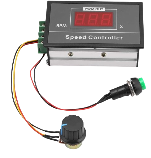
The PWM Speed Adjustable Controller is a versatile electronic component designed to regulate the speed of DC motors or other devices by utilizing Pulse Width Modulation (PWM) technology. By varying the width of the pulses in a signal, this controller enables precise and efficient control of motor speed without significant power loss. It is widely used in applications requiring variable speed control, such as robotics, fans, pumps, and other motor-driven systems.
Explore Projects Built with PWM Speed adjustable controller


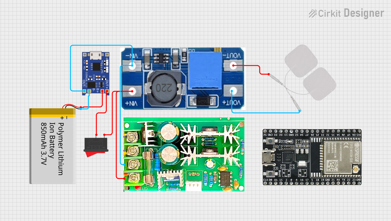
Explore Projects Built with PWM Speed adjustable controller
Common Applications and Use Cases
- DC motor speed control in robotics and automation systems
- Fan speed regulation in cooling systems
- Pump flow rate adjustment in fluid control systems
- LED dimming applications
- General-purpose power control in hobbyist and industrial projects
Technical Specifications
Below are the key technical details for the PWM Speed Adjustable Controller:
| Parameter | Value |
|---|---|
| Manufacturer | PWM |
| Manufacturer Part ID | PWM |
| Input Voltage Range | 6V to 30V DC |
| Output Current | Up to 10A |
| PWM Frequency | 15 kHz |
| Duty Cycle Range | 0% to 100% |
| Efficiency | >90% |
| Operating Temperature | -20°C to 60°C |
| Dimensions | 60mm x 40mm x 25mm |
Pin Configuration and Descriptions
The PWM Speed Adjustable Controller typically has the following pin configuration:
| Pin Name | Description |
|---|---|
| VIN+ | Positive input voltage terminal (connect to the positive terminal of the power supply). |
| VIN- | Negative input voltage terminal (connect to the ground of the power supply). |
| OUT+ | Positive output terminal (connect to the positive terminal of the motor or load). |
| OUT- | Negative output terminal (connect to the ground of the motor or load). |
| Potentiometer | Used to adjust the duty cycle and control the speed of the motor. |
Usage Instructions
How to Use the Component in a Circuit
Power Supply Connection:
- Connect the positive terminal of the DC power supply to the
VIN+pin. - Connect the ground terminal of the DC power supply to the
VIN-pin. - Ensure the input voltage is within the specified range (6V to 30V DC).
- Connect the positive terminal of the DC power supply to the
Load Connection:
- Connect the positive terminal of the motor or load to the
OUT+pin. - Connect the ground terminal of the motor or load to the
OUT-pin.
- Connect the positive terminal of the motor or load to the
Adjusting Speed:
- Use the onboard potentiometer to adjust the duty cycle of the PWM signal.
- Turning the potentiometer clockwise increases the duty cycle, resulting in higher motor speed.
- Turning it counterclockwise decreases the duty cycle, reducing motor speed.
Testing:
- Power on the circuit and observe the motor's behavior as you adjust the potentiometer.
- Ensure the motor operates smoothly without overheating.
Important Considerations and Best Practices
- Voltage Compatibility: Ensure the input voltage matches the motor's rated voltage to avoid damage.
- Current Rating: Verify that the motor's current draw does not exceed the controller's maximum output current (10A).
- Heat Dissipation: For high-current applications, ensure proper ventilation or use a heatsink to prevent overheating.
- Polarity: Double-check the polarity of all connections to avoid damaging the controller or motor.
- Noise Filtering: If the motor generates electrical noise, consider adding capacitors across the motor terminals to suppress interference.
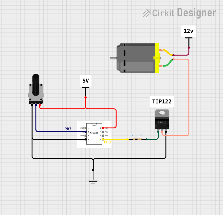
Example: Connecting to an Arduino UNO
The PWM Speed Adjustable Controller can also be controlled via an Arduino UNO by replacing the onboard potentiometer with a PWM signal from the Arduino. Below is an example code snippet:
// Example code to control a PWM Speed Adjustable Controller using Arduino UNO
// Connect Arduino PWM pin (e.g., D9) to the controller's potentiometer input

const int pwmPin = 9; // Define the PWM output pin

void setup() {
  pinMode(pwmPin, OUTPUT); // Set the PWM pin as an output
}

void loop() {
  // Gradually increase motor speed
  for (int dutyCycle = 0; dutyCycle <= 255; dutyCycle++) {
    analogWrite(pwmPin, dutyCycle); // Write PWM signal to the controller
    delay(10); // Small delay for smooth speed transition
  }

  // Gradually decrease motor speed
  for (int dutyCycle = 255; dutyCycle >= 0; dutyCycle--) {
    analogWrite(pwmPin, dutyCycle); // Write PWM signal to the controller
    delay(10); // Small delay for smooth speed transition
  }
}
Troubleshooting and FAQs
Common Issues and Solutions
Motor Does Not Start:
- Cause: Incorrect wiring or insufficient input voltage.
- Solution: Double-check all connections and ensure the input voltage is within the specified range.
Motor Runs at Full Speed Regardless of Adjustment:
- Cause: Faulty potentiometer or incorrect connection.
- Solution: Inspect the potentiometer and ensure it is properly connected.
Controller Overheats:
- Cause: Excessive current draw or poor ventilation.
- Solution: Ensure the motor's current draw does not exceed 10A and improve ventilation.
PWM Signal Interference:
- Cause: Electrical noise from the motor.
- Solution: Add capacitors across the motor terminals to suppress noise.
FAQs
Q1: Can this controller be used with AC motors?
A1: No, this controller is designed for DC motors only. Using it with AC motors may damage the controller.
Q2: What happens if I exceed the maximum current rating?
A2: Exceeding the 10A current rating can cause the controller to overheat or fail. Always ensure the motor's current draw is within the specified limit.
Q3: Can I use an external PWM signal instead of the potentiometer?
A3: Yes, you can replace the potentiometer with an external PWM signal, such as one generated by an Arduino or other microcontroller.
Q4: Is the controller waterproof?
A4: No, the controller is not waterproof. Use it in a dry environment or enclose it in a waterproof housing if necessary.