Cirkit Designer Logo
Cirkit Designer
Your all-in-one circuit design IDE
Home / 
Component Documentation

How to Use JSY-MK194G: Examples, Pinouts, and Specs

Image of JSY-MK194G
Cirkit Designer LogoDesign with JSY-MK194G in Cirkit Designer

Introduction

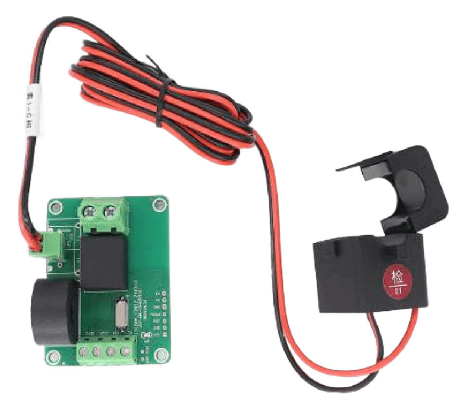
The JSY-MK194G is a compact, high-performance relay module designed for switching applications. It features a low control voltage and can handle high current loads, making it ideal for use in automation and control systems. This versatile component is commonly used in industrial equipment, home automation, and robotics, where reliable switching of high-power devices is required.

Explore Projects Built with JSY-MK194G

Use Cirkit Designer to design, explore, and prototype these projects online. Some projects support real-time simulation. Click "Open Project" to start designing instantly!
Lilygo 7670e-Based Smart Interface with LCD Display and Keypad
Image of Paower: A project utilizing JSY-MK194G in a practical application
This circuit features a Lilygo 7670e microcontroller interfaced with a 16x2 I2C LCD for display, a 4X4 membrane matrix keypad for input, and an arcade button for additional control. It also includes a 4G antenna and a GPS antenna for communication and location tracking capabilities.
Cirkit Designer LogoOpen Project in Cirkit Designer
Wireless Joystick-Controlled Interface with Arduino Nano and NRF24L01
Image of Transmitter 11: A project utilizing JSY-MK194G in a practical application
This circuit features an Arduino Nano interfaced with a KY-023 Dual Axis Joystick Module for analog input, and an NRF24L01 module for wireless communication. The joystick provides x and y-axis control signals to the Arduino's analog inputs and a switch signal to a digital input, while the NRF24L01 enables the Arduino to communicate with other devices wirelessly. The 2x 18650 batteries supply power to the Arduino, which in turn powers the joystick and the NRF24L01 module.
Cirkit Designer LogoOpen Project in Cirkit Designer
Battery-Powered ESP32-C3 Interactive Control Panel
Image of GTV-Transmitter Advanced: A project utilizing JSY-MK194G in a practical application
This circuit features an ESP32-C3 microcontroller connected to various input devices and an OLED display. The input devices include two KY-023 Dual Axis Joystick Modules for directional input and a Rotary Encoder for incremental input, both interfaced with the ESP32-C3's GPIO pins. The circuit also includes a power management system with a Polymer Lithium Ion Battery, a JST connector, and a toggle switch to control power to an LED indicator.
Cirkit Designer LogoOpen Project in Cirkit Designer
Arduino Nano-Based Wireless Joystick and Motion Controller
Image of hand gesture: A project utilizing JSY-MK194G in a practical application
This circuit features an Arduino Nano microcontroller interfaced with an HC-05 Bluetooth module, an MPU-6050 accelerometer/gyroscope, and a KY-023 Dual Axis Joystick Module. The Arduino Nano is powered by a 9V battery through a rocker switch and communicates with the HC-05 for Bluetooth connectivity, reads joystick positions from the KY-023 module via analog inputs, and communicates with the MPU-6050 over I2C to capture motion data. The circuit is likely designed for wireless control and motion sensing applications, such as a remote-controlled robot or a game controller.
Cirkit Designer LogoOpen Project in Cirkit Designer

Explore Projects Built with JSY-MK194G

Use Cirkit Designer to design, explore, and prototype these projects online. Some projects support real-time simulation. Click "Open Project" to start designing instantly!
Image of Paower: A project utilizing JSY-MK194G in a practical application
Lilygo 7670e-Based Smart Interface with LCD Display and Keypad
This circuit features a Lilygo 7670e microcontroller interfaced with a 16x2 I2C LCD for display, a 4X4 membrane matrix keypad for input, and an arcade button for additional control. It also includes a 4G antenna and a GPS antenna for communication and location tracking capabilities.
Cirkit Designer LogoOpen Project in Cirkit Designer
Image of Transmitter 11: A project utilizing JSY-MK194G in a practical application
Wireless Joystick-Controlled Interface with Arduino Nano and NRF24L01
This circuit features an Arduino Nano interfaced with a KY-023 Dual Axis Joystick Module for analog input, and an NRF24L01 module for wireless communication. The joystick provides x and y-axis control signals to the Arduino's analog inputs and a switch signal to a digital input, while the NRF24L01 enables the Arduino to communicate with other devices wirelessly. The 2x 18650 batteries supply power to the Arduino, which in turn powers the joystick and the NRF24L01 module.
Cirkit Designer LogoOpen Project in Cirkit Designer
Image of GTV-Transmitter Advanced: A project utilizing JSY-MK194G in a practical application
Battery-Powered ESP32-C3 Interactive Control Panel
This circuit features an ESP32-C3 microcontroller connected to various input devices and an OLED display. The input devices include two KY-023 Dual Axis Joystick Modules for directional input and a Rotary Encoder for incremental input, both interfaced with the ESP32-C3's GPIO pins. The circuit also includes a power management system with a Polymer Lithium Ion Battery, a JST connector, and a toggle switch to control power to an LED indicator.
Cirkit Designer LogoOpen Project in Cirkit Designer
Image of hand gesture: A project utilizing JSY-MK194G in a practical application
Arduino Nano-Based Wireless Joystick and Motion Controller
This circuit features an Arduino Nano microcontroller interfaced with an HC-05 Bluetooth module, an MPU-6050 accelerometer/gyroscope, and a KY-023 Dual Axis Joystick Module. The Arduino Nano is powered by a 9V battery through a rocker switch and communicates with the HC-05 for Bluetooth connectivity, reads joystick positions from the KY-023 module via analog inputs, and communicates with the MPU-6050 over I2C to capture motion data. The circuit is likely designed for wireless control and motion sensing applications, such as a remote-controlled robot or a game controller.
Cirkit Designer LogoOpen Project in Cirkit Designer

Technical Specifications

The JSY-MK194G relay module is designed to provide robust performance in a variety of applications. Below are its key technical specifications:

General Specifications

  • Relay Type: Electromechanical
  • Control Voltage: 5V DC
  • Operating Current: 70mA (typical)
  • Switching Voltage (Load): Up to 250V AC or 30V DC
  • Switching Current (Load): Up to 10A
  • Contact Type: SPDT (Single Pole Double Throw)
  • Isolation: Optocoupler-based isolation between control and load sides
  • Dimensions: 50mm x 25mm x 18mm
  • Mounting: PCB or screw terminal

Pin Configuration and Descriptions

The JSY-MK194G module has a simple pinout for easy integration into circuits. Below is the pin configuration:

Pin Name Description
VCC Connect to the 5V DC power supply for the relay module.
GND Connect to the ground of the power supply.
IN Control signal input. A HIGH signal (5V) activates the relay.
NO Normally Open contact. Connect the load here for switching when the relay is ON.
NC Normally Closed contact. Connect the load here for switching when the relay is OFF.
COM Common contact. Connect this to the power source or load.

Usage Instructions

The JSY-MK194G is straightforward to use in a variety of circuits. Follow the steps below to integrate it into your project:

Connecting the Relay Module

  1. Power the Module: Connect the VCC pin to a 5V DC power supply and the GND pin to the ground.
  2. Control Signal: Connect the IN pin to a microcontroller (e.g., Arduino UNO) or any other control circuit capable of providing a 5V HIGH signal.
  3. Load Connections:
    • For devices that should turn ON when the relay is activated, connect the load between the NO (Normally Open) and COM (Common) pins.
    • For devices that should turn OFF when the relay is activated, connect the load between the NC (Normally Closed) and COM pins.

Example Circuit with Arduino UNO

Below is an example of how to use the JSY-MK194G with an Arduino UNO to control a 220V AC light bulb:

Circuit Diagram

  • VCC: Connect to Arduino's 5V pin.
  • GND: Connect to Arduino's GND pin.
  • IN: Connect to Arduino's digital pin 7.
  • Load: Connect the light bulb to the NO and COM pins of the relay.

Arduino Code

// Example code to control the JSY-MK194G relay module with an Arduino UNO

#define RELAY_PIN 7  // Define the digital pin connected to the relay module

void setup() {
  pinMode(RELAY_PIN, OUTPUT);  // Set the relay pin as an output
  digitalWrite(RELAY_PIN, LOW);  // Ensure the relay is OFF at startup
}

void loop() {
  digitalWrite(RELAY_PIN, HIGH);  // Turn the relay ON
  delay(5000);  // Keep the relay ON for 5 seconds
  digitalWrite(RELAY_PIN, LOW);  // Turn the relay OFF
  delay(5000);  // Keep the relay OFF for 5 seconds
}

Important Considerations

  • Isolation: Ensure proper isolation between the control and load sides to prevent damage to the microcontroller or control circuit.
  • Flyback Diode: If switching an inductive load (e.g., motor), use a flyback diode across the load to protect the relay contacts from voltage spikes.
  • Power Ratings: Do not exceed the relay's maximum voltage and current ratings to avoid damage or failure.

Troubleshooting and FAQs

Common Issues and Solutions

  1. Relay Not Activating:

    • Ensure the control signal (IN pin) is receiving a proper HIGH signal (5V).
    • Verify that the VCC and GND connections are secure and providing the correct voltage.
  2. Load Not Switching:

    • Check the wiring of the load to the NO/NC and COM pins.
    • Ensure the load's voltage and current are within the relay's rated specifications.
  3. Relay Stuck in One State:

    • Inspect the relay contacts for damage or wear, especially if switching high-power loads frequently.
    • Verify that the control signal is toggling correctly.
  4. Noise or Interference:

    • Use a capacitor (e.g., 0.1µF) across the relay's VCC and GND pins to filter out noise.
    • Ensure proper grounding in the circuit.

FAQs

Q1: Can the JSY-MK194G be used with a 3.3V control signal?
A1: No, the JSY-MK194G requires a 5V control signal to activate the relay. Use a level shifter if your control circuit operates at 3.3V.

Q2: Is the relay suitable for switching DC motors?
A2: Yes, but ensure the motor's voltage and current are within the relay's rated limits. Use a flyback diode to protect the relay from voltage spikes.

Q3: Can I use the relay to switch both AC and DC loads?
A3: Yes, the JSY-MK194G can switch AC loads up to 250V and DC loads up to 30V, provided the current does not exceed 10A.

Q4: How do I know if the relay is ON or OFF?
A4: The JSY-MK194G typically includes an onboard LED indicator that lights up when the relay is activated.

By following this documentation, you can effectively integrate the JSY-MK194G into your projects and troubleshoot common issues with ease.