Cirkit Designer Logo
Cirkit Designer
Your all-in-one circuit design IDE
Home / 
Component Documentation

How to Use Eye Track VR v4 mini: Examples, Pinouts, and Specs

Image of Eye Track VR v4 mini
Cirkit Designer LogoDesign with Eye Track VR v4 mini in Cirkit Designer

Introduction

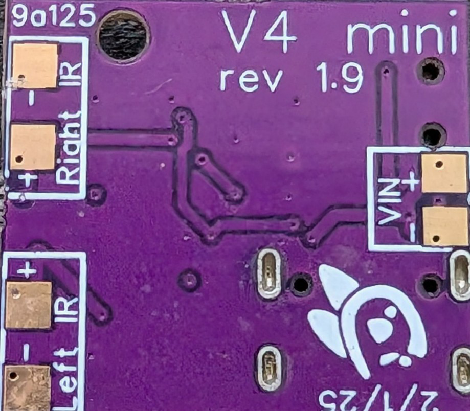
The Eye Track VR v4 Mini (Manufacturer Part ID: ETVR V4 Mini) is a compact and high-performance eye-tracking device designed specifically for virtual reality (VR) applications. Manufactured by Eye Track VR, this component enables precise gaze detection and interaction, enhancing the immersive experience in VR environments. Its small form factor makes it ideal for integration into VR headsets, AR glasses, and other wearable devices.

Explore Projects Built with Eye Track VR v4 mini

Use Cirkit Designer to design, explore, and prototype these projects online. Some projects support real-time simulation. Click "Open Project" to start designing instantly!
ESP32-Based Eye Pressure Monitor with OLED Display and Multiple Sensors
Image of test4: A project utilizing Eye Track VR v4 mini in a practical application
This circuit is designed to monitor eye pressure and deformation using a photodiode, a TCRT 5000 IR sensor, and a VL53L0X time-of-flight distance sensor. The ESP32 microcontroller reads sensor data, processes it to determine eye pressure status, and displays the results on a 0.96" OLED screen. It includes safety features, sensor calibration, and the ability to display sensor values and eye pressure status in real-time.
Cirkit Designer LogoOpen Project in Cirkit Designer
Beelink Mini S12 N95 and Arduino UNO Based Fingerprint Authentication System with ESP32 CAM
Image of design 3: A project utilizing Eye Track VR v4 mini in a practical application
This circuit features a Beelink MINI S12 N95 computer connected to a 7-inch display via HDMI for video output and two USB connections for power and touch screen functionality. An Arduino UNO is interfaced with a fingerprint scanner for biometric input. The Beelink MINI S12 N95 is powered by a PC power supply, which in turn is connected to a 240V power source. Additionally, an ESP32 CAM module is powered and programmed via a USB plug and an FTDI programmer, respectively, for wireless camera capabilities.
Cirkit Designer LogoOpen Project in Cirkit Designer
Arduino UNO-Based Eye Pressure Monitor with OLED Display and TOF Sensor
Image of test1: A project utilizing Eye Track VR v4 mini in a practical application
This circuit is designed to measure eye pressure and display the status on a 0.96" OLED screen, using an Arduino UNO as the central processing unit. It includes a TOF10120 sensor for distance measurement and a TCRT 5000 IR sensor for detecting surface changes, both interfacing with the Arduino. A 9V battery powers the system, with a rocker switch to control power flow, and the Arduino manages sensor data processing and OLED display output to indicate eye pressure as high, normal, or low.
Cirkit Designer LogoOpen Project in Cirkit Designer
Adafruit ItsyBitsy M4 Dual GC9A01 Display Animated Eyes
Image of Eyes: A project utilizing Eye Track VR v4 mini in a practical application
This circuit features an Adafruit ItsyBitsy M4 microcontroller connected to two GC9A01 displays. The microcontroller drives the displays to render animated eyes, with the code handling eye movements, blinks, and iris scaling. The displays share common control signals, and the microcontroller coordinates their operation to create synchronized visual effects.
Cirkit Designer LogoOpen Project in Cirkit Designer

Explore Projects Built with Eye Track VR v4 mini

Use Cirkit Designer to design, explore, and prototype these projects online. Some projects support real-time simulation. Click "Open Project" to start designing instantly!
Image of test4: A project utilizing Eye Track VR v4 mini in a practical application
ESP32-Based Eye Pressure Monitor with OLED Display and Multiple Sensors
This circuit is designed to monitor eye pressure and deformation using a photodiode, a TCRT 5000 IR sensor, and a VL53L0X time-of-flight distance sensor. The ESP32 microcontroller reads sensor data, processes it to determine eye pressure status, and displays the results on a 0.96" OLED screen. It includes safety features, sensor calibration, and the ability to display sensor values and eye pressure status in real-time.
Cirkit Designer LogoOpen Project in Cirkit Designer
Image of design 3: A project utilizing Eye Track VR v4 mini in a practical application
Beelink Mini S12 N95 and Arduino UNO Based Fingerprint Authentication System with ESP32 CAM
This circuit features a Beelink MINI S12 N95 computer connected to a 7-inch display via HDMI for video output and two USB connections for power and touch screen functionality. An Arduino UNO is interfaced with a fingerprint scanner for biometric input. The Beelink MINI S12 N95 is powered by a PC power supply, which in turn is connected to a 240V power source. Additionally, an ESP32 CAM module is powered and programmed via a USB plug and an FTDI programmer, respectively, for wireless camera capabilities.
Cirkit Designer LogoOpen Project in Cirkit Designer
Image of test1: A project utilizing Eye Track VR v4 mini in a practical application
Arduino UNO-Based Eye Pressure Monitor with OLED Display and TOF Sensor
This circuit is designed to measure eye pressure and display the status on a 0.96" OLED screen, using an Arduino UNO as the central processing unit. It includes a TOF10120 sensor for distance measurement and a TCRT 5000 IR sensor for detecting surface changes, both interfacing with the Arduino. A 9V battery powers the system, with a rocker switch to control power flow, and the Arduino manages sensor data processing and OLED display output to indicate eye pressure as high, normal, or low.
Cirkit Designer LogoOpen Project in Cirkit Designer
Image of Eyes: A project utilizing Eye Track VR v4 mini in a practical application
Adafruit ItsyBitsy M4 Dual GC9A01 Display Animated Eyes
This circuit features an Adafruit ItsyBitsy M4 microcontroller connected to two GC9A01 displays. The microcontroller drives the displays to render animated eyes, with the code handling eye movements, blinks, and iris scaling. The displays share common control signals, and the microcontroller coordinates their operation to create synchronized visual effects.
Cirkit Designer LogoOpen Project in Cirkit Designer

Common Applications and Use Cases

  • Virtual Reality (VR): Enhances user interaction by tracking gaze direction for immersive experiences.
  • Augmented Reality (AR): Enables intuitive control and interaction in AR applications.
  • Gaming: Provides gaze-based controls for next-generation gaming experiences.
  • Medical Research: Used in cognitive studies and vision-related research.
  • Accessibility Tools: Assists users with disabilities by enabling hands-free control.

Technical Specifications

Key Technical Details

Parameter Value
Manufacturer Eye Track VR
Part ID ETVR V4 Mini
Power Supply Voltage 3.3V to 5V
Power Consumption 150mW (typical)
Communication Interface I2C, UART
Sampling Rate Up to 120 Hz
Field of View (FoV) 90° horizontal, 70° vertical
Accuracy ±0.5°
Operating Temperature -10°C to 50°C
Dimensions 25mm x 15mm x 5mm
Weight 3 grams

Pin Configuration and Descriptions

Pin Number Pin Name Description
1 VCC Power supply input (3.3V to 5V)
2 GND Ground connection
3 SDA I2C data line
4 SCL I2C clock line
5 TX UART transmit line
6 RX UART receive line
7 INT Interrupt output for event notifications
8 NC Not connected (reserved for future use)

Usage Instructions

How to Use the Component in a Circuit

  1. Power Supply: Connect the VCC pin to a 3.3V or 5V power source and the GND pin to ground.
  2. Communication Interface:
    • For I2C communication, connect the SDA and SCL pins to the corresponding I2C pins on your microcontroller.
    • For UART communication, connect the TX and RX pins to the UART pins on your microcontroller.
  3. Interrupt Pin (Optional): Use the INT pin to receive event notifications, such as gaze detection or calibration completion.
  4. Pull-Up Resistors: Ensure that the I2C lines (SDA and SCL) have appropriate pull-up resistors (typically 4.7kΩ).
  5. Mounting: Secure the Eye Track VR v4 Mini in your VR headset or device using adhesive or screws, ensuring the sensor is aligned with the user's eyes.

Important Considerations and Best Practices

  • Calibration: Perform an initial calibration to ensure accurate gaze tracking. Most VR software includes built-in calibration routines.
  • Ambient Light: Avoid direct exposure to bright light sources, as they may interfere with the sensor's accuracy.
  • Cable Management: Use short, shielded cables to minimize noise and interference in the communication lines.
  • Firmware Updates: Check the manufacturer's website for firmware updates to improve performance and compatibility.

Example Code for Arduino UNO (I2C Communication)

#include <Wire.h> // Include the Wire library for I2C communication

#define ETVR_I2C_ADDRESS 0x42 // Default I2C address for Eye Track VR v4 Mini

void setup() {
  Wire.begin(); // Initialize I2C communication
  Serial.begin(9600); // Initialize serial communication for debugging

  // Send initialization command to the Eye Track VR v4 Mini
  Wire.beginTransmission(ETVR_I2C_ADDRESS);
  Wire.write(0x01); // Example command: Start tracking
  Wire.endTransmission();

  Serial.println("Eye Track VR v4 Mini initialized.");
}

void loop() {
  Wire.requestFrom(ETVR_I2C_ADDRESS, 4); // Request 4 bytes of gaze data

  if (Wire.available() == 4) {
    int x = Wire.read(); // Read horizontal gaze position
    int y = Wire.read(); // Read vertical gaze position
    int pupilSize = Wire.read(); // Read pupil size
    int status = Wire.read(); // Read status byte

    // Print the gaze data to the serial monitor
    Serial.print("Gaze X: ");
    Serial.print(x);
    Serial.print(", Gaze Y: ");
    Serial.print(y);
    Serial.print(", Pupil Size: ");
    Serial.print(pupilSize);
    Serial.print(", Status: ");
    Serial.println(status);
  }

  delay(100); // Delay to reduce I2C bus load
}

Troubleshooting and FAQs

Common Issues and Solutions

  1. No Data Received:

    • Cause: Incorrect I2C address or wiring.
    • Solution: Verify the I2C address (default is 0x42) and check the connections.
  2. Inaccurate Gaze Tracking:

    • Cause: Misalignment of the sensor or improper calibration.
    • Solution: Ensure the sensor is properly aligned with the user's eyes and perform a calibration.
  3. Interference or Noise:

    • Cause: Long or unshielded cables.
    • Solution: Use short, shielded cables and ensure proper grounding.
  4. Device Not Detected:

    • Cause: Insufficient power supply or faulty connections.
    • Solution: Check the power supply voltage (3.3V to 5V) and ensure all connections are secure.

FAQs

  • Q: Can the Eye Track VR v4 Mini be used with Raspberry Pi?
    A: Yes, the device supports I2C and UART communication, which are compatible with Raspberry Pi.

  • Q: What is the maximum sampling rate?
    A: The device supports a sampling rate of up to 120 Hz.

  • Q: Does the device require external drivers?
    A: No, the device is plug-and-play with most microcontrollers and VR platforms. However, specific software may require additional libraries.

  • Q: Can it track both eyes simultaneously?
    A: No, the Eye Track VR v4 Mini is designed for single-eye tracking. For dual-eye tracking, consider other models from Eye Track VR.


This concludes the documentation for the Eye Track VR v4 Mini. For further assistance, refer to the manufacturer's website or contact their support team.