How to Use MD10C R3: Examples, Pinouts, and Specs
Introduction
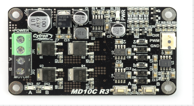
The MD10C R3 is a robust motor driver designed to control DC motors with high efficiency and reliability. It is capable of driving a single brushed DC motor with a continuous current of up to 13A and a peak current of 30A. The MD10C R3 is equipped with a wide input voltage range and supports both PWM (Pulse Width Modulation) and direction control signals, making it ideal for robotics, automation systems, and other motor control applications.
Explore Projects Built with MD10C R3


Explore Projects Built with MD10C R3
Common Applications and Use Cases
- Robotics and mobile platforms
- Conveyor belt systems
- Automated gates and doors
- Industrial automation
- Hobbyist motor control projects
Technical Specifications
Key Technical Details
| Parameter | Specification |
|---|---|
| Operating Voltage Range | 5V to 30V |
| Continuous Current | 13A |
| Peak Current | 30A |
| Control Signal Voltage | 3.3V or 5V logic compatible |
| PWM Frequency Range | Up to 20 kHz |
| Dimensions | 84mm x 62mm x 25mm |
| Weight | 70g |
| Protection Features | Overcurrent and thermal shutdown |
Pin Configuration and Descriptions
| Pin Name | Pin Type | Description |
|---|---|---|
| VM | Power Input | Motor power supply input (5V to 30V). |
| GND | Power Ground | Ground connection for the motor power supply. |
| MOTOR+ | Motor Output | Positive terminal of the DC motor. |
| MOTOR- | Motor Output | Negative terminal of the DC motor. |
| PWM | Control Input | PWM signal input for speed control (3.3V or 5V logic). |
| DIR | Control Input | Direction control input (3.3V or 5V logic). |
| VCC | Power Output | 5V output for external logic circuits (max 100mA). |
| GND (Logic) | Logic Ground | Ground connection for control signals. |
Usage Instructions
How to Use the MD10C R3 in a Circuit
- Power Supply: Connect the motor power supply to the
VMpin and the ground to theGNDpin. Ensure the voltage is within the 5V to 30V range. - Motor Connection: Connect the DC motor terminals to the
MOTOR+andMOTOR-pins. - Control Signals:
- Connect the
PWMpin to a PWM-capable output pin of your microcontroller for speed control. - Connect the
DIRpin to a digital output pin of your microcontroller to control the motor's direction.
- Connect the
- Logic Ground: Connect the
GND (Logic)pin to the ground of your microcontroller to ensure a common reference. - Optional: Use the
VCCpin to power external logic circuits if needed (max 100mA).
Important Considerations and Best Practices
- Ensure the motor's current and voltage ratings are within the MD10C R3's specifications.
- Use appropriate heat dissipation methods (e.g., heatsinks) if operating near the maximum current limit.
- Avoid reversing the polarity of the power supply or motor connections to prevent damage.
- Use a fuse or circuit breaker for additional protection in high-current applications.
Example Code for Arduino UNO
Below is an example of how to control the MD10C R3 with an Arduino UNO:
// Define pin connections
const int pwmPin = 9;  // PWM signal pin connected to MD10C R3's PWM pin
const int dirPin = 8;  // Direction control pin connected to MD10C R3's DIR pin

void setup() {
  // Set pin modes
  pinMode(pwmPin, OUTPUT);
  pinMode(dirPin, OUTPUT);
}

void loop() {
  // Rotate motor forward at 50% speed
  digitalWrite(dirPin, HIGH);  // Set direction to forward
  analogWrite(pwmPin, 128);    // Set PWM duty cycle to 50% (128/255)

  delay(2000);  // Run for 2 seconds

  // Rotate motor backward at 75% speed
  digitalWrite(dirPin, LOW);   // Set direction to backward
  analogWrite(pwmPin, 192);    // Set PWM duty cycle to 75% (192/255)

  delay(2000);  // Run for 2 seconds
}
Troubleshooting and FAQs
Common Issues and Solutions
Motor Not Running:
- Verify that the power supply voltage is within the specified range (5V to 30V).
- Check all connections, especially the motor and control signal pins.
- Ensure the PWM signal is being generated correctly by the microcontroller.
Motor Running in the Wrong Direction:
- Check the logic level of the
DIRpin. HIGH typically corresponds to forward, and LOW to reverse. - Verify the motor connections to
MOTOR+andMOTOR-.
- Check the logic level of the
Overheating:
- Ensure the motor's current draw does not exceed the MD10C R3's continuous current rating (13A).
- Use a heatsink or active cooling if operating near the maximum current limit.
PWM Signal Not Detected:
- Confirm that the PWM frequency is within the supported range (up to 20 kHz).
- Ensure the PWM signal voltage level matches the MD10C R3's logic compatibility (3.3V or 5V).
FAQs
Can I use the MD10C R3 with a 3.3V microcontroller? Yes, the MD10C R3 is compatible with both 3.3V and 5V logic levels.
What happens if the motor draws more than 13A continuously? The MD10C R3 has overcurrent protection and may shut down to prevent damage. Ensure your motor's current requirements are within the specified limits.
Can I control two motors with one MD10C R3? No, the MD10C R3 is designed to control a single brushed DC motor.
Is reverse polarity protection included? No, reverse polarity protection is not included. Double-check your connections before powering the circuit.