
How to Use Power Supply: Examples, Pinouts, and Specs
 Design with Power Supply in Cirkit Designer
Introduction
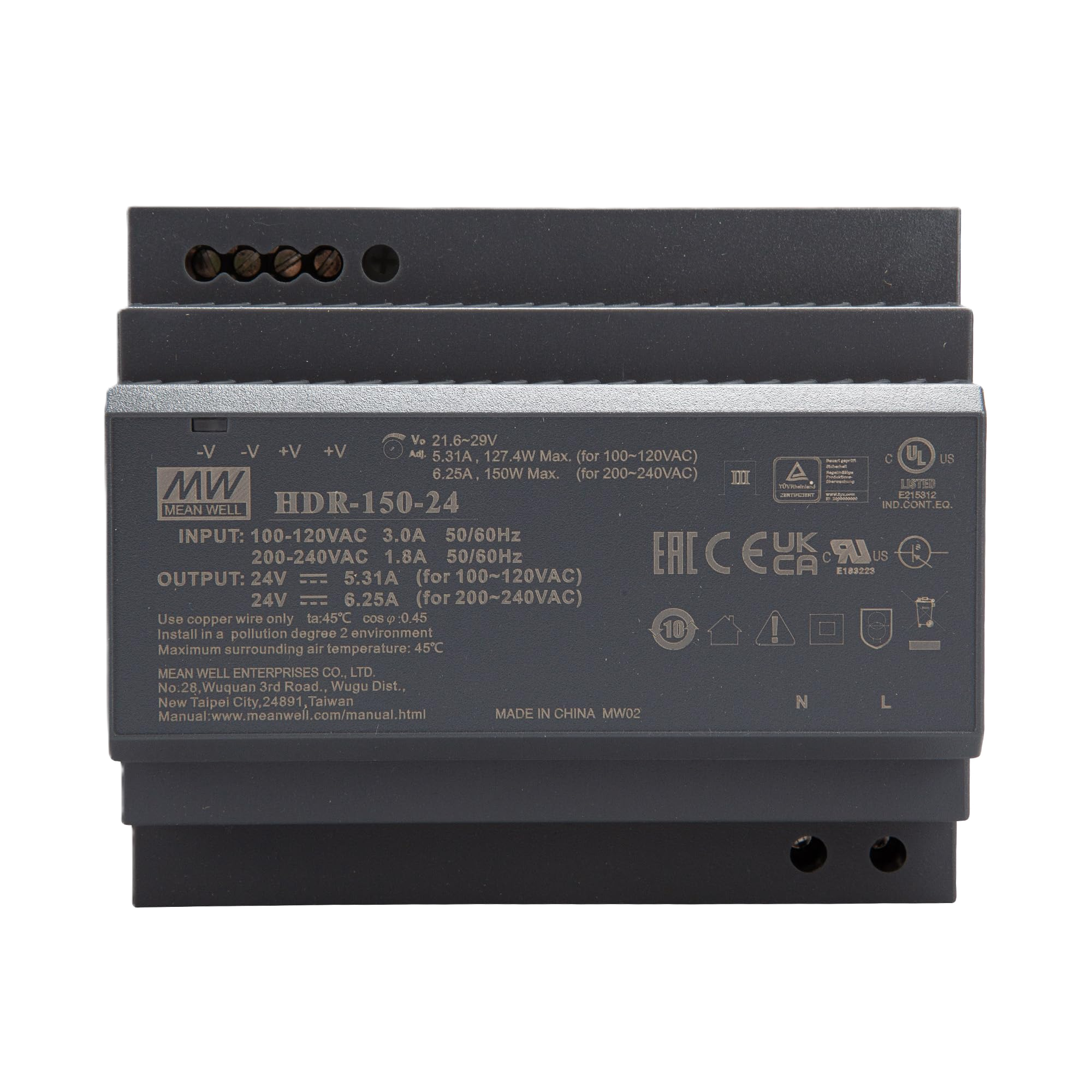
The MEAN WELL HDR-150-24 is a highly efficient, compact DIN rail power supply designed to provide reliable electrical energy to circuits. It converts AC mains voltage into a stable 24V DC output, suitable for powering a wide range of electronic devices and systems. With its slim design and high efficiency, the HDR-150-24 is ideal for industrial automation, building automation, and general-purpose applications requiring a dependable power source.
Explore Projects Built with Power Supply
 Open Project in Cirkit Designer
 Open Project in Cirkit Designer
 Open Project in Cirkit Designer
 Open Project in Cirkit Designer
Explore Projects Built with Power Supply
Open Project in Cirkit DesignerOpen Project in Cirkit DesignerOpen Project in Cirkit DesignerOpen Project in Cirkit DesignerCommon Applications and Use Cases
- Industrial automation systems
- Building automation and control
- LED lighting systems
- Security and surveillance equipment
- Laboratory and testing equipment
- General-purpose DC power supply for electronic circuits
Technical Specifications
The following table outlines the key technical details of the MEAN WELL HDR-150-24 power supply:
| Parameter | Value |
|---|---|
| Manufacturer | MEAN WELL |
| Part Number | HDR-150-24 |
| Input Voltage Range | 85-264 VAC / 120-370 VDC |
| Output Voltage | 24V DC |
| Output Current | 6.5A |
| Output Power | 156W |
| Efficiency | Up to 91% |
| Dimensions | 105mm x 90mm x 54mm (W x H x D) |
| Operating Temperature | -30°C to +70°C |
| Protection Features | Overload, Overvoltage, Short Circuit |
| Mounting Type | DIN Rail (TS-35/7.5 or TS-35/15) |
| Certifications | UL, CE, EAC, RoHS |
Pin Configuration and Descriptions
The HDR-150-24 features screw terminal connections for input and output. The pin configuration is as follows:
| Pin | Label | Description |
|---|---|---|
| 1 | L | AC Line Input |
| 2 | N | AC Neutral Input |
| 3 | FG | Frame Ground (Earth) |
| 4 | +V | Positive DC Output |
| 5 | -V | Negative DC Output |
Usage Instructions
How to Use the HDR-150-24 in a Circuit
- Mounting: Secure the HDR-150-24 onto a DIN rail (TS-35/7.5 or TS-35/15) in your enclosure or control panel.
- Input Connection:
- Connect the AC mains supply to the
L(Line) andN(Neutral) terminals. - Connect the
FG(Frame Ground) terminal to the earth ground for safety.
- Connect the AC mains supply to the
- Output Connection:
- Connect the
+Vterminal to the positive input of your load or circuit. - Connect the
-Vterminal to the negative input of your load or circuit.
- Connect the
- Adjust Output Voltage (Optional):
- Use the built-in potentiometer to fine-tune the output voltage within the range of 21.6V to 26.4V DC.
- Power On:
- Ensure all connections are secure, then power on the AC mains supply. The LED indicator on the power supply will light up to indicate proper operation.
Important Considerations and Best Practices
- Input Voltage: Ensure the input voltage is within the specified range (85-264 VAC or 120-370 VDC).
- Load Requirements: Do not exceed the maximum output current of 6.5A or the total output power of 156W.
- Ventilation: Install the power supply in a well-ventilated area to prevent overheating.
- Safety: Always disconnect the power supply from the mains before making any wiring changes.
- Protection Features: The HDR-150-24 includes overload, overvoltage, and short-circuit protection. If the power supply shuts down due to a fault, disconnect the load, resolve the issue, and restart the power supply.
Example: Connecting to an Arduino UNO
The HDR-150-24 can be used to power an Arduino UNO and other peripherals. Below is an example of how to connect it:
- Connect the
+Vterminal of the HDR-150-24 to the Arduino'sVINpin. - Connect the
-Vterminal of the HDR-150-24 to the Arduino'sGNDpin. - Ensure the output voltage is set to 24V DC.
Here is a simple Arduino sketch to blink an LED when powered by the HDR-150-24:
// Simple LED Blink Example
// This code blinks an LED connected to pin 13 of the Arduino UNO.
// Ensure the Arduino is powered by the HDR-150-24 via the VIN and GND pins.

void setup() {
  pinMode(13, OUTPUT); // Set pin 13 as an output
}

void loop() {
  digitalWrite(13, HIGH); // Turn the LED on
  delay(1000);            // Wait for 1 second
  digitalWrite(13, LOW);  // Turn the LED off
  delay(1000);            // Wait for 1 second
}
Troubleshooting and FAQs
Common Issues and Solutions
No Output Voltage:
- Check the AC input connections (
LandN) and ensure the mains power is on. - Verify that the
FGterminal is properly grounded. - Inspect the load connections (
+Vand-V) for loose or incorrect wiring. - Ensure the load does not exceed the maximum output current or power rating.
- Check the AC input connections (
Power Supply Shuts Down:
- This may be due to overload, overvoltage, or a short circuit. Disconnect the load, resolve the issue, and restart the power supply.
Overheating:
- Ensure the power supply is installed in a well-ventilated area.
- Check for obstructions around the power supply that may block airflow.
LED Indicator Not Lit:
- Verify that the input voltage is within the specified range.
- Check for blown fuses or tripped circuit breakers in the AC mains supply.
FAQs
Q: Can the HDR-150-24 be used with a battery as the input source?
A: Yes, the HDR-150-24 supports DC input voltage in the range of 120-370 VDC. Ensure the battery voltage is within this range.
Q: Is the output voltage adjustable?
A: Yes, the output voltage can be adjusted between 21.6V and 26.4V DC using the built-in potentiometer.
Q: Can I use this power supply to charge batteries?
A: The HDR-150-24 is not specifically designed for battery charging. Use a dedicated battery charger for optimal performance and safety.
Q: What type of DIN rail is compatible with this power supply?
A: The HDR-150-24 is compatible with TS-35/7.5 or TS-35/15 DIN rails.
Q: Does the power supply include a fan?
A: No, the HDR-150-24 is fanless and relies on natural air convection for cooling.