
How to Use 12V 25GA-370 DC Gear Motor: Examples, Pinouts, and Specs
 Design with 12V 25GA-370 DC Gear Motor in Cirkit Designer
Introduction
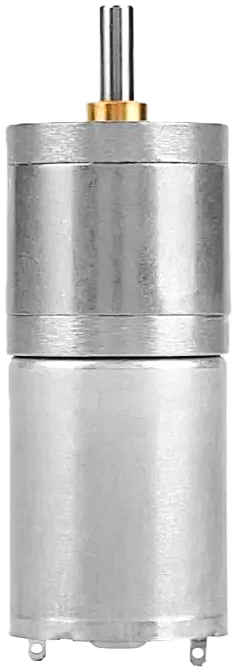
The 12V 25GA-370 DC Gear Motor is a compact and efficient motor designed to deliver high torque at low speeds. Its integrated gearbox allows for precise control, making it ideal for applications such as robotics, automation systems, conveyor belts, and small mechanical devices. This motor is widely used in projects requiring reliable and consistent rotational motion.
Explore Projects Built with 12V 25GA-370 DC Gear Motor
 Open Project in Cirkit Designer
 Open Project in Cirkit Designer
 Open Project in Cirkit Designer
 Open Project in Cirkit Designer
Explore Projects Built with 12V 25GA-370 DC Gear Motor
Open Project in Cirkit DesignerOpen Project in Cirkit DesignerOpen Project in Cirkit DesignerOpen Project in Cirkit DesignerCommon Applications
- Robotics (e.g., robotic arms, mobile robots)
- Automated systems (e.g., conveyor belts, sorting machines)
- DIY projects and hobbyist applications
- Small-scale industrial machinery
- Precision control systems
Technical Specifications
Below are the key technical details of the 12V 25GA-370 DC Gear Motor:
| Parameter | Value |
|---|---|
| Operating Voltage | 12V DC |
| No-Load Speed | ~200 RPM (varies by model) |
| Rated Torque | ~1.5 kg.cm |
| Stall Torque | ~5 kg.cm |
| No-Load Current | ~0.15 A |
| Stall Current | ~1.2 A |
| Gearbox Type | Planetary Gearbox |
| Shaft Diameter | 4 mm |
| Shaft Length | 10 mm |
| Motor Dimensions | 25 mm (diameter) x 37 mm (length) |
| Weight | ~120 g |
Pin Configuration and Descriptions
The motor has two terminals for electrical connections:
| Pin | Description |
|---|---|
| Terminal 1 (Red) | Positive terminal for power input (+12V) |
| Terminal 2 (Black) | Negative terminal for power input (GND) |
Note: The polarity of the terminals determines the direction of rotation. Reversing the polarity will reverse the motor's rotation.
Usage Instructions
How to Use the Motor in a Circuit
- Power Supply: Connect the motor to a 12V DC power source. Ensure the power supply can provide sufficient current (at least 1.5 A) to handle the motor's stall current.
- Direction Control: Use an H-bridge motor driver (e.g., L298N or L293D) to control the motor's direction and speed. The H-bridge allows you to reverse the polarity of the motor terminals.
- Speed Control: Implement Pulse Width Modulation (PWM) using a microcontroller (e.g., Arduino UNO) to control the motor's speed.
Important Considerations
- Current Limiting: Ensure the power supply and motor driver can handle the stall current to avoid damage.
- Heat Dissipation: Prolonged operation at high torque may cause the motor to heat up. Allow for proper ventilation or cooling.
- Load Matching: Avoid overloading the motor beyond its rated torque to prevent mechanical or electrical failure.
- Polarity: Double-check the polarity of the connections to avoid unintended rotation or damage.
Example: Connecting to an Arduino UNO
Below is an example of how to control the motor's speed and direction using an Arduino UNO and an L298N motor driver:
// Define motor control pins
const int ENA = 9;  // PWM pin for speed control
const int IN1 = 7;  // Direction control pin 1
const int IN2 = 8;  // Direction control pin 2

void setup() {
  // Set motor control pins as outputs
  pinMode(ENA, OUTPUT);
  pinMode(IN1, OUTPUT);
  pinMode(IN2, OUTPUT);
}

void loop() {
  // Rotate motor clockwise at 50% speed
  analogWrite(ENA, 128); // Set PWM duty cycle (0-255)
  digitalWrite(IN1, HIGH);
  digitalWrite(IN2, LOW);
  delay(2000); // Run for 2 seconds

  // Rotate motor counterclockwise at 75% speed
  analogWrite(ENA, 192); // Set PWM duty cycle (0-255)
  digitalWrite(IN1, LOW);
  digitalWrite(IN2, HIGH);
  delay(2000); // Run for 2 seconds

  // Stop the motor
  analogWrite(ENA, 0); // Set PWM duty cycle to 0
  delay(2000); // Wait for 2 seconds
}
Note: Ensure the motor driver is properly connected to the Arduino and the motor. Refer to the motor driver's datasheet for wiring details.
Troubleshooting and FAQs
Common Issues and Solutions
Motor Does Not Rotate
- Cause: Insufficient power supply or loose connections.
- Solution: Verify the power supply voltage and current. Check all connections.
Motor Rotates in the Wrong Direction
- Cause: Incorrect polarity of the motor terminals.
- Solution: Swap the connections of the motor terminals or adjust the H-bridge control signals.
Motor Overheats
- Cause: Prolonged operation at high torque or insufficient ventilation.
- Solution: Reduce the load on the motor or improve cooling.
Motor Vibrates but Does Not Rotate
- Cause: Excessive load or mechanical obstruction.
- Solution: Remove the load and check for obstructions. Ensure the motor is not stalled.
PWM Control Not Working
- Cause: Incorrect PWM signal or motor driver configuration.
- Solution: Verify the PWM signal from the microcontroller and check the motor driver's datasheet.
FAQs
Q1: Can I use this motor with a 9V battery?
A1: While the motor may run on a 9V battery, it will not perform optimally. A 12V DC power supply is recommended for full performance.
Q2: What is the maximum load this motor can handle?
A2: The motor's rated torque is approximately 1.5 kg.cm. Avoid exceeding this value to prevent damage.
Q3: Can I control this motor without a motor driver?
A3: Directly connecting the motor to a power supply will make it run at full speed in one direction. For speed and direction control, a motor driver is required.
Q4: Is this motor suitable for continuous operation?
A4: Yes, but ensure proper cooling and avoid overloading to prevent overheating.
Q5: Can I use this motor for precise positioning?
A5: This motor is not designed for precise positioning. For such applications, consider using a stepper motor or a DC motor with an encoder.