How to Use ESP-WROOM32 (30 pin): Examples, Pinouts, and Specs
Introduction
The ESP-WROOM32 is a powerful Wi-Fi and Bluetooth module based on the ESP32 chip, designed for high-performance and low-power IoT applications. With its 30-pin configuration, it offers versatile connectivity options, making it suitable for a wide range of projects, from smart home devices to industrial automation systems. The module integrates dual-core processing, a rich set of peripherals, and robust wireless communication capabilities, making it a popular choice among developers and hobbyists.
Explore Projects Built with ESP-WROOM32 (30 pin)


Explore Projects Built with ESP-WROOM32 (30 pin)
Common Applications and Use Cases
- IoT devices and smart home automation
- Wireless sensor networks
- Wearable electronics
- Industrial control systems
- Robotics and drones
- Prototyping and development of connected devices
Technical Specifications
Key Technical Details
| Specification | Value |
|---|---|
| Microcontroller | ESP32 dual-core Xtensa LX6 |
| Clock Speed | Up to 240 MHz |
| Flash Memory | 4 MB (varies by model) |
| SRAM | 520 KB |
| Wireless Connectivity | Wi-Fi 802.11 b/g/n, Bluetooth v4.2 BR/EDR |
| Operating Voltage | 3.3V |
| Input Voltage Range | 3.0V - 3.6V |
| GPIO Pins | 30 |
| Communication Interfaces | UART, SPI, I2C, I2S, PWM, ADC, DAC |
| ADC Resolution | 12-bit |
| Operating Temperature Range | -40°C to 85°C |
| Power Consumption (Wi-Fi) | 160 mA (active), <10 µA (deep sleep) |
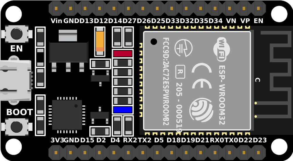
Pin Configuration and Descriptions
| Pin Number | Pin Name | Description |
|---|---|---|
| 1 | EN | Enable pin (active high) |
| 2 | IO36 (VP) | ADC1 channel 0, GPIO36 |
| 3 | IO39 (VN) | ADC1 channel 3, GPIO39 |
| 4 | IO34 | ADC1 channel 6, GPIO34 |
| 5 | IO35 | ADC1 channel 7, GPIO35 |
| 6 | IO32 | ADC1 channel 4, GPIO32 |
| 7 | IO33 | ADC1 channel 5, GPIO33 |
| 8 | IO25 | DAC1, GPIO25 |
| 9 | IO26 | DAC2, GPIO26 |
| 10 | IO27 | GPIO27 |
| 11 | IO14 | HSPI CLK, GPIO14 |
| 12 | IO12 | HSPI MISO, GPIO12 |
| 13 | IO13 | HSPI MOSI, GPIO13 |
| 14 | IO15 | HSPI CS, GPIO15 |
| 15 | IO2 | GPIO2 |
| 16 | IO0 | GPIO0, boot mode selection |
| 17 | IO4 | GPIO4 |
| 18 | IO16 | GPIO16 |
| 19 | IO17 | GPIO17 |
| 20 | IO5 | GPIO5 |
| 21 | IO18 | GPIO18 |
| 22 | IO19 | GPIO19 |
| 23 | IO21 | GPIO21 |
| 24 | IO22 | GPIO22 |
| 25 | IO23 | GPIO23 |
| 26 | GND | Ground |
| 27 | 3V3 | 3.3V power supply |
| 28 | VIN | Input voltage (5V) |
| 29 | TXD0 | UART0 TX |
| 30 | RXD0 | UART0 RX |
Usage Instructions
How to Use the ESP-WROOM32 in a Circuit
- Power Supply: Connect the VIN pin to a 5V power source or the 3V3 pin to a regulated 3.3V supply. Ensure the ground (GND) is connected to the circuit's ground.
- Programming: Use a USB-to-serial adapter or a development board (e.g., ESP32 DevKit) to program the module. The UART0 pins (TXD0 and RXD0) are used for communication with the host computer.
- GPIO Usage: Configure the GPIO pins as input, output, or alternate functions (e.g., ADC, PWM) in your code. Be cautious of the maximum current ratings for each pin.
- Wi-Fi and Bluetooth: Use the ESP-IDF or Arduino IDE to configure and enable wireless communication. Libraries like
WiFi.handBluetoothSerial.hsimplify the process.
Important Considerations and Best Practices
- Voltage Levels: Ensure all GPIO pins operate at 3.3V logic levels. Use level shifters if interfacing with 5V devices.
- Boot Mode: GPIO0 must be pulled low during boot to enter programming mode.
- Antenna Placement: Avoid placing metal objects near the onboard antenna to ensure optimal wireless performance.
- Deep Sleep Mode: Use deep sleep mode to minimize power consumption in battery-powered applications.
Example Code for Arduino UNO Integration
Below is an example of using the ESP-WROOM32 to connect to a Wi-Fi network:
#include <WiFi.h> // Include the Wi-Fi library

const char* ssid = "Your_SSID";       // Replace with your Wi-Fi network name
const char* password = "Your_Password"; // Replace with your Wi-Fi password

void setup() {
  Serial.begin(115200); // Initialize serial communication at 115200 baud
  delay(1000);          // Wait for the serial monitor to initialize

  Serial.println("Connecting to Wi-Fi...");
  WiFi.begin(ssid, password); // Start Wi-Fi connection

  while (WiFi.status() != WL_CONNECTED) {
    delay(500); // Wait for connection
    Serial.print(".");
  }

  Serial.println("\nWi-Fi connected!");
  Serial.print("IP Address: ");
  Serial.println(WiFi.localIP()); // Print the assigned IP address
}

void loop() {
  // Add your main code here
}
Troubleshooting and FAQs
Common Issues and Solutions
Module Not Responding:
- Ensure the EN pin is connected to 3.3V.
- Verify the power supply provides sufficient current (at least 500 mA).
- Check the UART connections (TXD0 to RX, RXD0 to TX).
Wi-Fi Connection Fails:
- Double-check the SSID and password in your code.
- Ensure the router is within range and supports 2.4 GHz Wi-Fi.
GPIO Pin Not Working:
- Verify the pin mode is correctly configured in the code.
- Avoid using reserved pins (e.g., GPIO6-GPIO11 are used for flash memory).
Overheating:
- Ensure the module is not drawing excessive current.
- Provide adequate ventilation or a heatsink if necessary.
FAQs
Can the ESP-WROOM32 operate on 5V logic? No, the GPIO pins are designed for 3.3V logic. Use level shifters for 5V devices.
What is the maximum Wi-Fi range? The range depends on environmental factors but typically extends up to 100 meters in open spaces.
How do I reset the module? Pull the EN pin low momentarily or press the reset button on the development board.
Can I use the ESP-WROOM32 with the Arduino IDE? Yes, the ESP32 core for Arduino IDE supports the ESP-WROOM32 module. Install the core via the Arduino Boards Manager.