Cirkit Designer Logo
Cirkit Designer
Your all-in-one circuit design IDE
Home / 
Component Documentation

How to Use Regulator XL 4015 with LCD Display with heatsink: Examples, Pinouts, and Specs

Image of Regulator XL 4015 with LCD Display with heatsink
Cirkit Designer LogoDesign with Regulator XL 4015 with LCD Display with heatsink in Cirkit Designer

Introduction

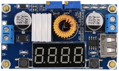
The Regulator XL 4015 with LCD Display is a high-efficiency, adjustable step-down (buck) DC/DC converter with an integrated LCD that provides real-time feedback on voltage and current parameters. It is equipped with a heatsink to ensure efficient heat dissipation during operation. This component is commonly used in applications requiring precise voltage regulation, such as battery charging, power supplies for electronic devices, and DIY electronics projects.

Explore Projects Built with Regulator XL 4015 with LCD Display with heatsink

Use Cirkit Designer to design, explore, and prototype these projects online. Some projects support real-time simulation. Click "Open Project" to start designing instantly!
ESP32-Based Smart Energy Monitoring and Control System
Image of SMART SOCKET: A project utilizing Regulator XL 4015 with LCD Display with heatsink in a practical application
This circuit is designed to monitor AC voltage and current using ZMPT101B and ZMCT103C sensors, respectively, with an ESP32 microcontroller processing the sensor outputs. The XL4015 step-down module regulates the power supply to provide a stable voltage to the sensors, the ESP32, and an LCD I2C display. The ESP32 controls a 4-channel relay module for switching AC loads, and the system's operation can be interacted with via the LCD display and a push switch.
Cirkit Designer LogoOpen Project in Cirkit Designer
Solar-Powered Battery Charging System with LCD Voltage Regulation
Image of Solar charger: A project utilizing Regulator XL 4015 with LCD Display with heatsink in a practical application
This circuit consists of a solar panel and a 12V 5Ah battery connected to a step-down DC regulator with an LCD display. The solar panel and battery provide input power to the regulator, which steps down the voltage to a desired level for output.
Cirkit Designer LogoOpen Project in Cirkit Designer
Solar-Powered Battery Charging System with XL6009 Voltage Regulator
Image of SISTEMA DE ALIMENTACION Y CARGA SENSORES DS18B20 Y SENSOR DE TURBIDEZ: A project utilizing Regulator XL 4015 with LCD Display with heatsink in a practical application
This circuit features a solar panel ('Do solara') connected to a voltage regulator ('XL6009 Voltage Regulator') to stabilize the output voltage. The regulated voltage is available at a terminal block ('Terminal PCB 2 Pin') for further use. Additionally, a Li-ion battery ('18650 Li-ion Battery') is connected to the solar panel for charging, with the solar panel's output also routed through the voltage regulator.
Cirkit Designer LogoOpen Project in Cirkit Designer
Arduino-Controlled Incubator with Temperature Regulation and LCD Display
Image of Desine baru: A project utilizing Regulator XL 4015 with LCD Display with heatsink in a practical application
This is an Arduino UNO-based incubator control system designed to maintain a specified temperature. It uses a DHT22 sensor for temperature readings, a 5V relay to control heating, and an LCD for display. Users can set the desired temperature using pushbuttons, and the system automatically regulates the heater to maintain the set temperature.
Cirkit Designer LogoOpen Project in Cirkit Designer

Explore Projects Built with Regulator XL 4015 with LCD Display with heatsink

Use Cirkit Designer to design, explore, and prototype these projects online. Some projects support real-time simulation. Click "Open Project" to start designing instantly!
Image of SMART SOCKET: A project utilizing Regulator XL 4015 with LCD Display with heatsink in a practical application
ESP32-Based Smart Energy Monitoring and Control System
This circuit is designed to monitor AC voltage and current using ZMPT101B and ZMCT103C sensors, respectively, with an ESP32 microcontroller processing the sensor outputs. The XL4015 step-down module regulates the power supply to provide a stable voltage to the sensors, the ESP32, and an LCD I2C display. The ESP32 controls a 4-channel relay module for switching AC loads, and the system's operation can be interacted with via the LCD display and a push switch.
Cirkit Designer LogoOpen Project in Cirkit Designer
Image of Solar charger: A project utilizing Regulator XL 4015 with LCD Display with heatsink in a practical application
Solar-Powered Battery Charging System with LCD Voltage Regulation
This circuit consists of a solar panel and a 12V 5Ah battery connected to a step-down DC regulator with an LCD display. The solar panel and battery provide input power to the regulator, which steps down the voltage to a desired level for output.
Cirkit Designer LogoOpen Project in Cirkit Designer
Image of SISTEMA DE ALIMENTACION Y CARGA SENSORES DS18B20 Y SENSOR DE TURBIDEZ: A project utilizing Regulator XL 4015 with LCD Display with heatsink in a practical application
Solar-Powered Battery Charging System with XL6009 Voltage Regulator
This circuit features a solar panel ('Do solara') connected to a voltage regulator ('XL6009 Voltage Regulator') to stabilize the output voltage. The regulated voltage is available at a terminal block ('Terminal PCB 2 Pin') for further use. Additionally, a Li-ion battery ('18650 Li-ion Battery') is connected to the solar panel for charging, with the solar panel's output also routed through the voltage regulator.
Cirkit Designer LogoOpen Project in Cirkit Designer
Image of Desine baru: A project utilizing Regulator XL 4015 with LCD Display with heatsink in a practical application
Arduino-Controlled Incubator with Temperature Regulation and LCD Display
This is an Arduino UNO-based incubator control system designed to maintain a specified temperature. It uses a DHT22 sensor for temperature readings, a 5V relay to control heating, and an LCD for display. Users can set the desired temperature using pushbuttons, and the system automatically regulates the heater to maintain the set temperature.
Cirkit Designer LogoOpen Project in Cirkit Designer

Common Applications and Use Cases

  • DIY variable power supplies
  • Battery chargers
  • LED drivers
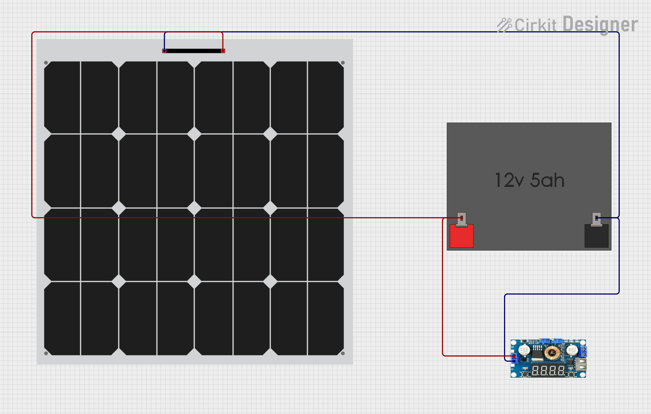
  • Solar power management
  • Electronics prototyping

Technical Specifications

Key Technical Details

  • Input Voltage: 4V to 38V DC
  • Output Voltage: 1.25V to 36V DC (adjustable)
  • Output Current: Up to 5A (with proper heat dissipation)
  • Conversion Efficiency: Up to 96%
  • Operating Frequency: 180kHz
  • Load Regulation: S (I) ≤ 0.8%
  • Voltage Regulation: S (u) ≤ 0.8%

Pin Configuration and Descriptions

Pin Number Name Description
1 IN+ Input Voltage Positive
2 IN- Input Voltage Negative
3 OUT+ Output Voltage Positive
4 OUT- Output Voltage Negative
5 ADJ Adjustment Pin (for voltage setting)
6 GND Ground

Usage Instructions

How to Use the Component in a Circuit

  1. Connect the input voltage to the IN+ and IN- pins, ensuring that the voltage is within the specified range.
  2. Connect the output load to the OUT+ and OUT- pins.
  3. Adjust the onboard potentiometer to set the desired output voltage. The LCD will display the current output voltage and current.
  4. Attach the heatsink to the XL 4015 chip to ensure adequate heat dissipation, especially when drawing high currents.

Important Considerations and Best Practices

  • Always verify input and output voltages with a multimeter before connecting sensitive loads.
  • Ensure that the input voltage is higher than the desired output voltage, as this is a step-down regulator.
  • Do not exceed the maximum input voltage and current ratings to prevent damage to the component.
  • Use adequate wiring for high-current applications to minimize voltage drops and overheating.
  • If the regulator is to be used near its maximum output current rating, ensure proper ventilation and consider adding additional cooling measures.

Troubleshooting and FAQs

Common Issues

  • Display not showing correct values: Check the connections to the LCD and ensure the potentiometer is functioning correctly.
  • Excessive heat generation: Ensure the heatsink is properly attached and that the current draw is within the specified limits.
  • Voltage output is unstable: Verify that the input voltage is stable and within the specified range. Check for any loose connections.

Solutions and Tips for Troubleshooting

  • If the output voltage cannot be adjusted, replace the potentiometer.
  • For overheating issues, reduce the load current or improve cooling.
  • Ensure all connections are secure and free from corrosion or damage.

FAQs

Q: Can I use this regulator to charge batteries? A: Yes, but ensure that the output voltage is set correctly for the battery type and that the charging current is within the battery's specifications.

Q: What is the purpose of the heatsink? A: The heatsink helps to dissipate heat generated by the regulator, especially when operating at high currents, to prevent overheating and ensure reliable operation.

Q: How accurate is the LCD display? A: The LCD display is generally accurate, but it is always recommended to verify the readings with a multimeter for critical applications.

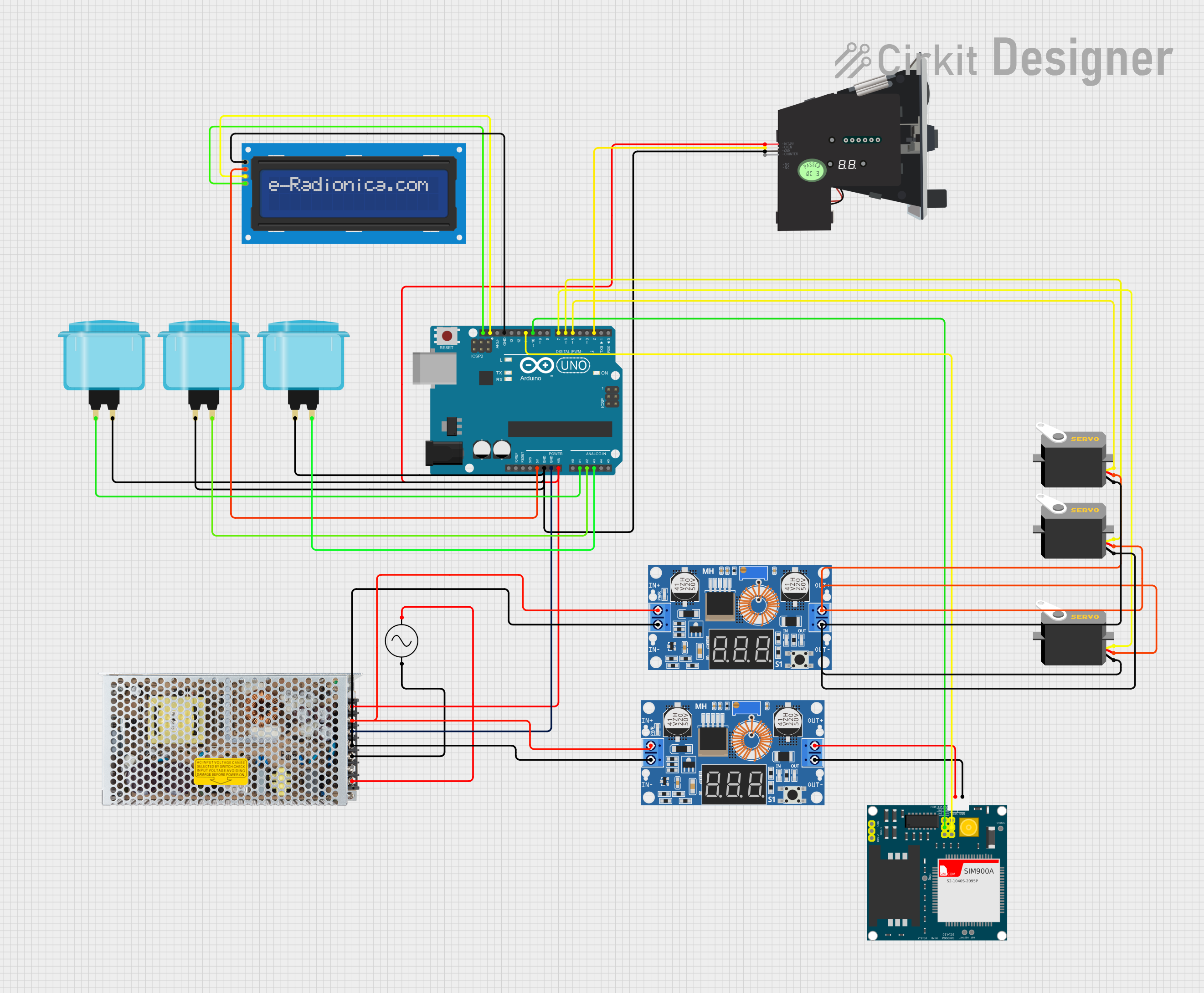
Example Arduino UNO Connection Code

// Note: This is a pseudo-code example to illustrate how you might control the XL 4015
// with an Arduino UNO for a simple application. The XL 4015 does not have digital control,
// so this code assumes you have an external digital potentiometer or DAC to adjust voltage.

#include <Wire.h>

// Replace with your digital potentiometer's I2C address or DAC settings
#define DIGITAL_POT_ADDRESS 0x00

void setup() {
  Wire.begin(); // Start I2C communication
  Serial.begin(9600); // Start serial communication for debugging
}

void loop() {
  // Set desired voltage output (in millivolts)
  int desiredVoltage = 5000; // 5V
  setOutputVoltage(desiredVoltage);
  delay(1000); // Wait for a second
}

// Function to set the output voltage of the XL 4015 via a digital potentiometer or DAC
void setOutputVoltage(int millivolts) {
  // Convert millivolts to a value your digital potentiometer or DAC understands
  // This will depend on your specific hardware and its resolution
  int digitalValue = map(millivolts, 0, 36000, 0, 1023); // Example conversion

  // Send the value to the digital potentiometer or DAC
  Wire.beginTransmission(DIGITAL_POT_ADDRESS);
  Wire.write(digitalValue);
  Wire.endTransmission();

  // Debug output
  Serial.print("Setting voltage to: ");
  Serial.print(millivolts);
  Serial.println(" mV");
}

Note: The above code is a hypothetical example and assumes the use of additional components like a digital potentiometer or DAC for voltage adjustment. The XL 4015 itself does not have digital control capabilities and is typically adjusted manually via an onboard potentiometer.