How to Use PCB_dimmer: Examples, Pinouts, and Specs
Introduction
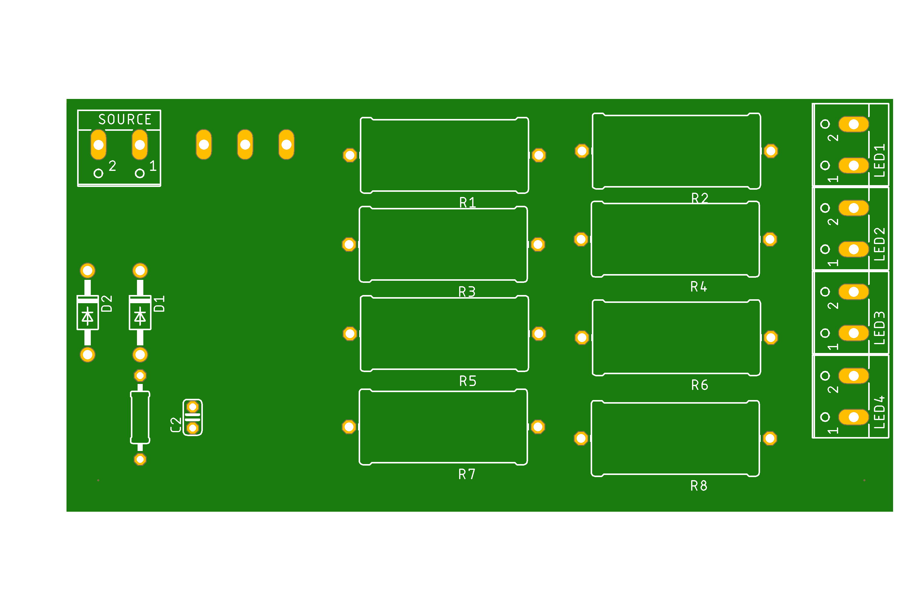
The PCB_dimmer by MAYO is a printed circuit board designed to control the brightness of lights by adjusting the power delivered to the load. It typically uses a triac or similar device to regulate the power flow, making it ideal for dimming incandescent, halogen, or certain types of dimmable LED lights. This component is compact, efficient, and easy to integrate into various lighting systems.
Explore Projects Built with PCB_dimmer
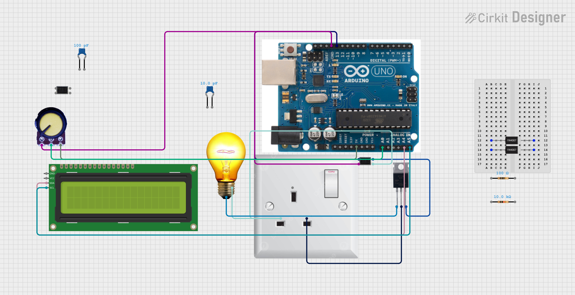
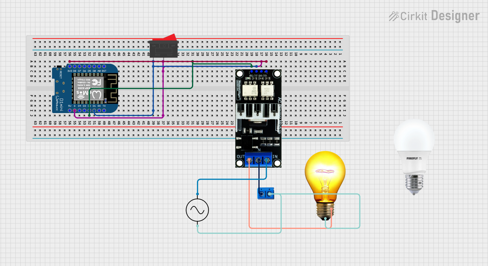

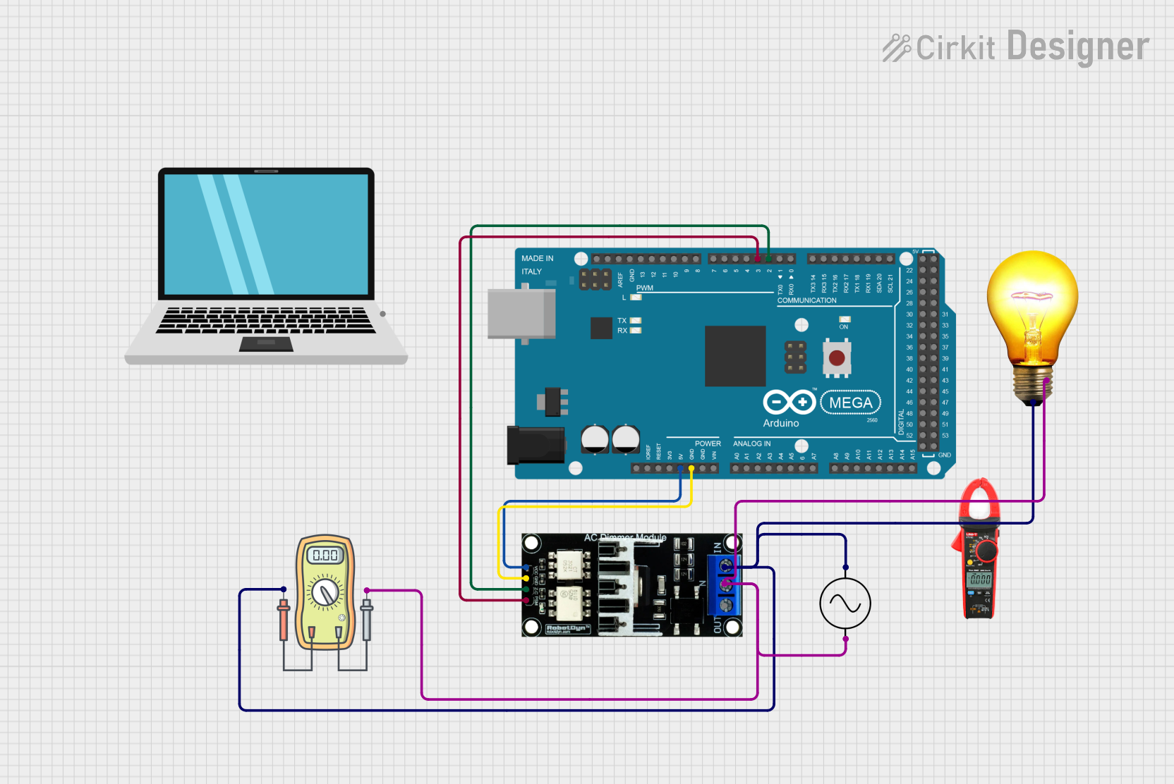
Explore Projects Built with PCB_dimmer
Common Applications and Use Cases
- Home lighting systems for adjustable brightness
- Stage lighting for dynamic ambiance control
- Industrial lighting where variable intensity is required
- Smart home automation projects
- Educational projects to demonstrate power control principles
Technical Specifications
The following table outlines the key technical details of the PCB_dimmer:
| Parameter | Value |
|---|---|
| Input Voltage | 110V AC to 240V AC |
| Output Voltage | Adjustable (dependent on input) |
| Maximum Load Power | 400W |
| Control Method | Phase-cut dimming (triac-based) |
| Operating Frequency | 50Hz / 60Hz |
| PCB Dimensions | 50mm x 40mm x 15mm |
| Operating Temperature | -10°C to 50°C |
Pin Configuration and Descriptions
The PCB_dimmer has the following pin configuration:
| Pin Name | Description |
|---|---|
| AC_IN_L | Live input from the AC power source |
| AC_IN_N | Neutral input from the AC power source |
| AC_OUT_L | Live output to the load (e.g., light bulb) |
| AC_OUT_N | Neutral output to the load (connected directly to AC_IN_N) |
| CTRL | Control input for dimming (e.g., potentiometer or microcontroller PWM signal) |
Usage Instructions
How to Use the PCB_dimmer in a Circuit
- Connect the Input Power:
- Connect the live wire of the AC power source to the
AC_IN_Lpin. - Connect the neutral wire of the AC power source to the
AC_IN_Npin.
- Connect the live wire of the AC power source to the
- Connect the Load:
- Connect the live wire of the load (e.g., light bulb) to the
AC_OUT_Lpin. - Connect the neutral wire of the load to the
AC_OUT_Npin.
- Connect the live wire of the load (e.g., light bulb) to the
- Control the Brightness:
- Use a potentiometer or a PWM signal from a microcontroller (e.g., Arduino) to the
CTRLpin to adjust the brightness.
- Use a potentiometer or a PWM signal from a microcontroller (e.g., Arduino) to the
- Power On:
- Ensure all connections are secure and power on the AC source. Adjust the control input to vary the brightness.
Important Considerations and Best Practices
- Safety First: Always handle the PCB_dimmer with care, as it operates at high AC voltages. Ensure proper insulation and avoid touching the board while powered.
- Load Compatibility: Verify that the connected load is dimmable and does not exceed the maximum power rating of 400W.
- Heat Dissipation: The triac may generate heat during operation. Ensure adequate ventilation or use a heatsink if necessary.
- PWM Control: If using a microcontroller, ensure the PWM signal is compatible with the dimmer's control input.
Example: Using PCB_dimmer with Arduino UNO
Below is an example of how to control the PCB_dimmer using an Arduino UNO and a PWM signal:
// Example code to control PCB_dimmer using Arduino UNO
// Connect the CTRL pin of the PCB_dimmer to pin 9 of the Arduino UNO

int dimmerPin = 9; // PWM pin connected to the CTRL pin of PCB_dimmer
int brightness = 0; // Brightness level (0-255)
int fadeAmount = 5; // Amount to increase/decrease brightness

void setup() {
  pinMode(dimmerPin, OUTPUT); // Set dimmerPin as an output
}

void loop() {
  analogWrite(dimmerPin, brightness); // Send PWM signal to dimmer

  // Adjust brightness for a fade effect
  brightness = brightness + fadeAmount;

  // Reverse direction of fade at the ends of the range
  if (brightness <= 0 || brightness >= 255) {
    fadeAmount = -fadeAmount;
  }

  delay(30); // Delay for smooth fading
}
Troubleshooting and FAQs
Common Issues and Solutions
The light does not turn on:
- Ensure the AC input and output connections are correct.
- Verify that the load is functional and compatible with the dimmer.
- Check the control input (e.g., potentiometer or PWM signal) for proper operation.
The light flickers:
- Ensure the load is dimmable and within the power rating of the dimmer.
- Check for loose connections or interference in the control signal.
The dimmer overheats:
- Verify that the load does not exceed the maximum power rating of 400W.
- Ensure proper ventilation or add a heatsink to the triac.
PWM control does not work:
- Confirm that the PWM signal frequency and voltage levels are compatible with the dimmer.
- Test the PWM output from the microcontroller using an oscilloscope or multimeter.
FAQs
Q: Can the PCB_dimmer be used with LED lights?
A: Yes, but only with dimmable LED lights that are compatible with phase-cut dimming.
Q: What happens if I exceed the maximum load power?
A: Exceeding the 400W limit may damage the dimmer or cause it to overheat. Always stay within the specified power rating.
Q: Can I use the PCB_dimmer with DC loads?
A: No, the PCB_dimmer is designed for AC loads only and is not suitable for DC applications.
Q: Is it safe to use the PCB_dimmer without a heatsink?
A: For loads below 200W, a heatsink may not be necessary. However, for higher loads, a heatsink is recommended to prevent overheating.
By following this documentation, you can safely and effectively use the PCB_dimmer by MAYO in your lighting projects.