How to Use Bio Amp Cable: Examples, Pinouts, and Specs
Introduction
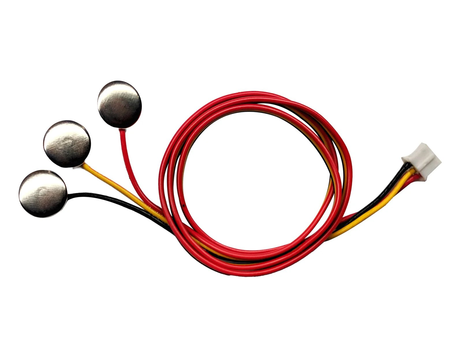
The Bio Amp Cable is a specialized cable designed for bioamplification applications. It is primarily used to connect electrodes to amplifiers in biomedical devices, ensuring minimal noise and high fidelity in signal transmission. This component is essential in applications where precise and clean signal acquisition is critical, such as in electrocardiography (ECG), electromyography (EMG), and electroencephalography (EEG) systems.
Explore Projects Built with Bio Amp Cable

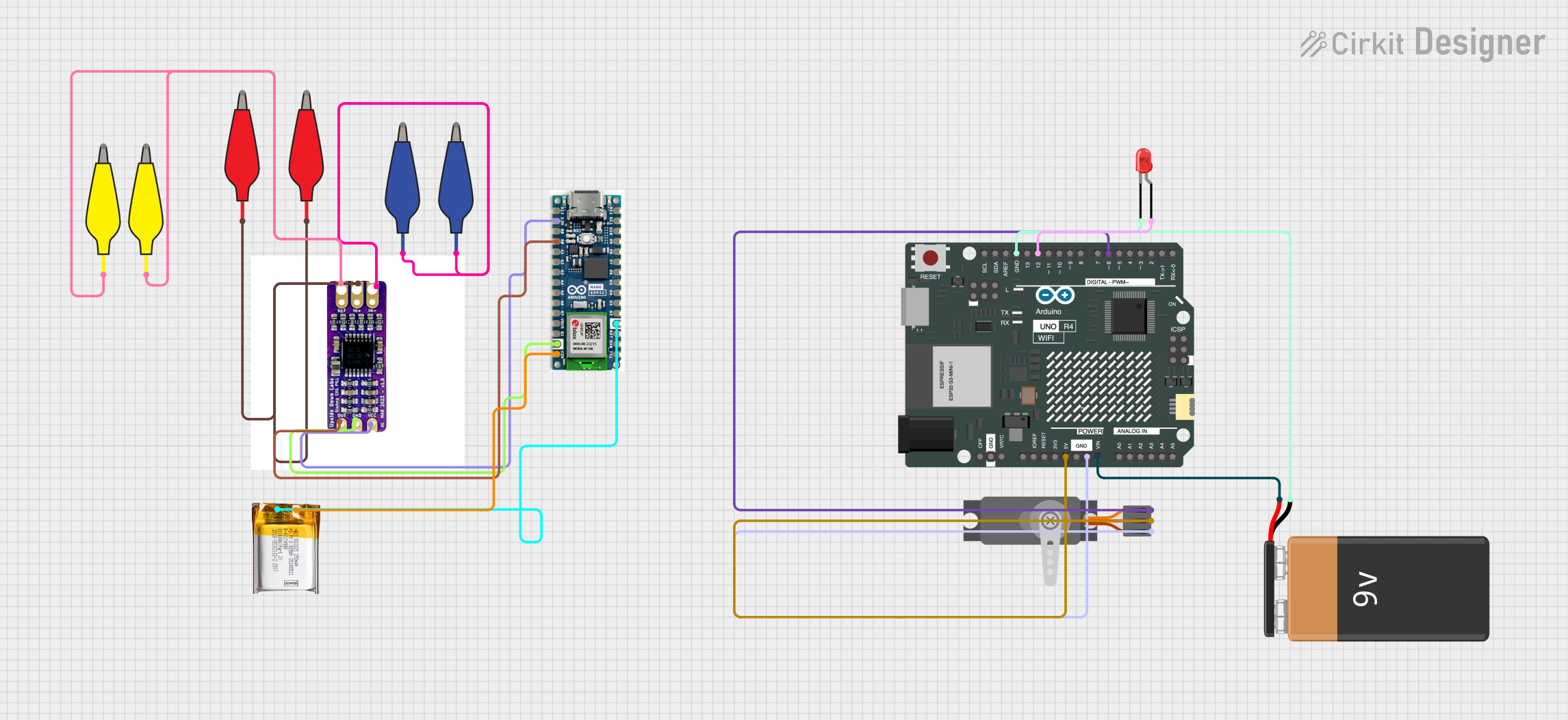
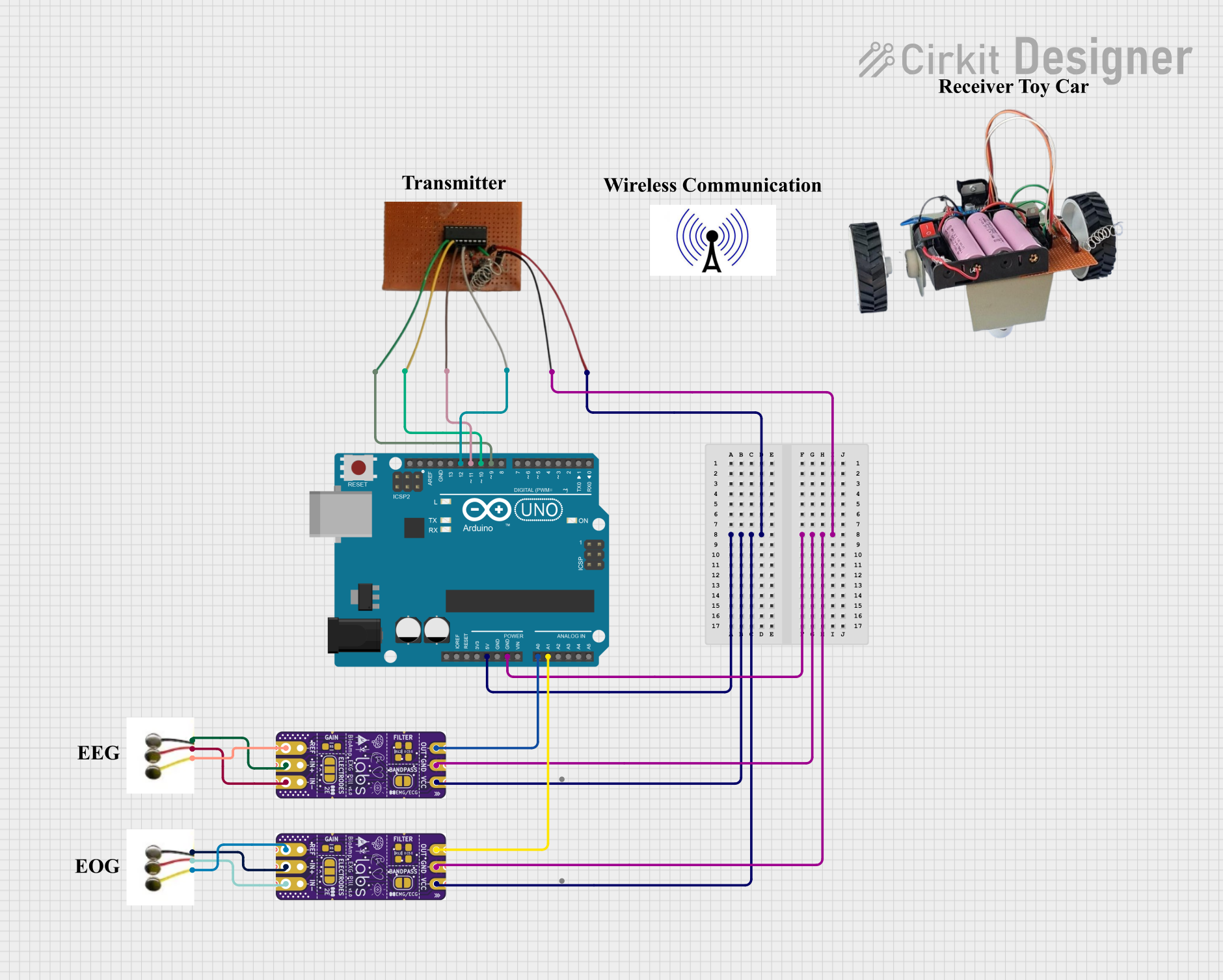
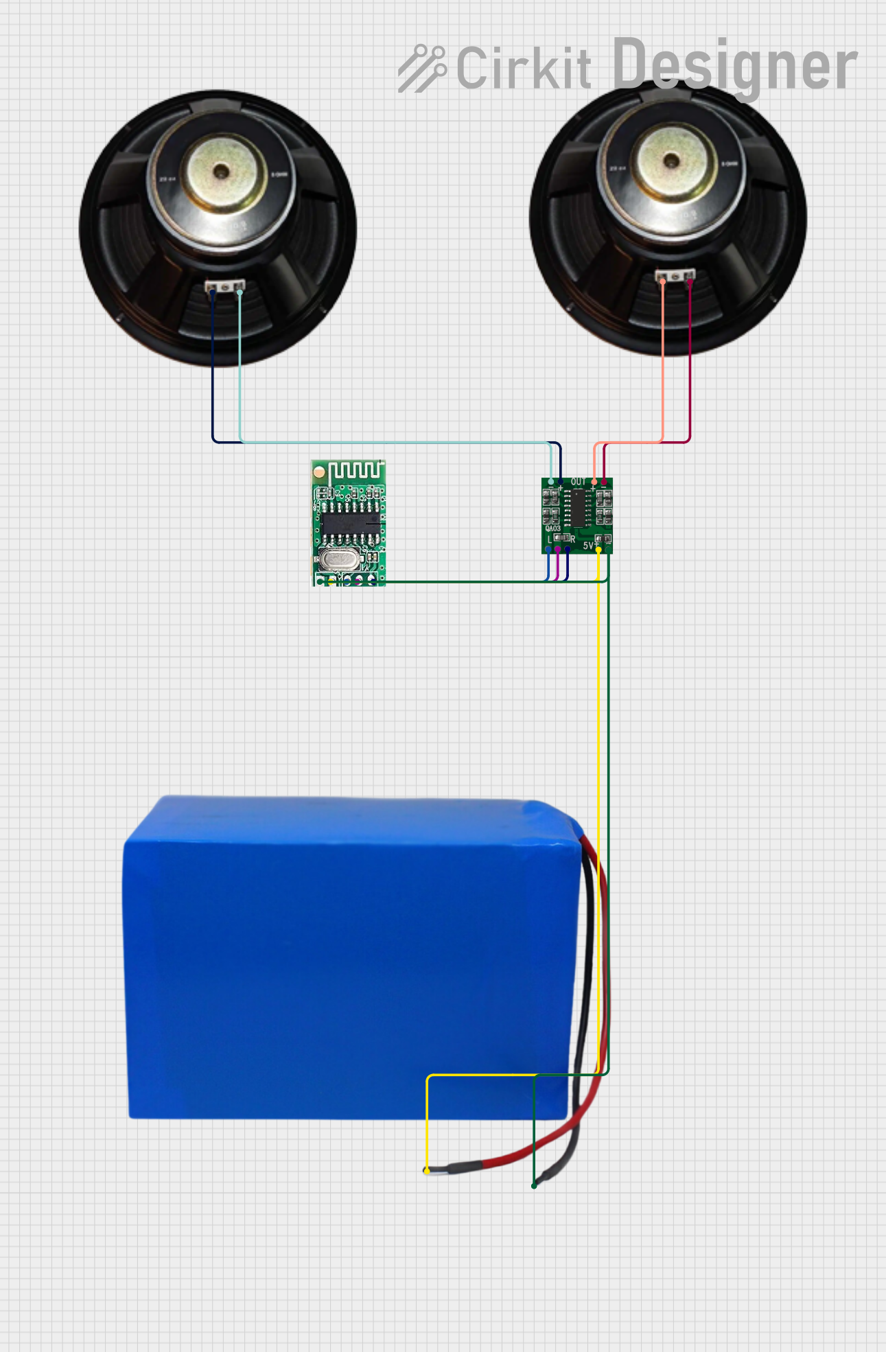
Explore Projects Built with Bio Amp Cable
Common Applications and Use Cases
- Medical Diagnostics: Used in ECG, EMG, and EEG devices for monitoring physiological signals.
- Biomedical Research: Facilitates the study of bioelectric signals in laboratory settings.
- Wearable Health Devices: Ensures reliable signal transmission in portable health monitoring systems.
- Rehabilitation Devices: Used in biofeedback systems for physical therapy and rehabilitation.
Technical Specifications
Key Technical Details
- Cable Type: Shielded, low-noise coaxial cable
- Length: Typically available in 1m, 2m, and 3m variants
- Connector Type: Standard 2mm or 4mm banana plugs, or custom connectors as required
- Impedance: 50Ω (typical)
- Signal Fidelity: High, with minimal signal attenuation
- Noise Rejection: >90 dB shielding effectiveness
- Operating Temperature: -20°C to 60°C
- Material: Medical-grade, flexible, and biocompatible insulation
Pin Configuration and Descriptions
The Bio Amp Cable typically has two or three conductors, depending on the application. Below is a general description of the pin configuration:
| Pin/Conductor | Description | Color Code |
|---|---|---|
| Signal (+) | Positive signal input from the electrode | Red |
| Signal (-) | Negative signal input (reference/ground) | Black |
| Shield | Cable shielding for noise rejection | Uninsulated (optional) |
Note: The exact pin configuration may vary depending on the specific cable model and application.
Usage Instructions
How to Use the Bio Amp Cable in a Circuit
- Connect Electrodes: Attach the electrodes to the patient or subject as per the device's instructions.
- Attach the Cable: Connect the Bio Amp Cable to the electrodes using the appropriate connectors (e.g., banana plugs).
- Connect to Amplifier: Plug the other end of the cable into the bioamplifier's input port, ensuring proper alignment of the connectors.
- Verify Connections: Ensure all connections are secure to avoid signal loss or noise interference.
- Power On the System: Turn on the bioamplifier and associated equipment to begin signal acquisition.
Important Considerations and Best Practices
- Minimize Movement: Avoid excessive movement of the cable during operation to reduce motion artifacts.
- Shielding: Ensure the shielding is properly grounded to maximize noise rejection.
- Cable Length: Use the shortest cable length possible to minimize signal attenuation.
- Cleaning: Clean the cable with a soft, damp cloth and avoid harsh chemicals to maintain its biocompatibility.
- Storage: Store the cable in a cool, dry place to prevent damage to the insulation.
Example: Using the Bio Amp Cable with an Arduino UNO
The Bio Amp Cable can be used with an Arduino UNO for basic bioelectric signal acquisition when paired with a bioamplifier. Below is an example of how to read an amplified signal using the Arduino's analog input:
// Example code to read bioelectric signals using Arduino UNO
// Ensure the Bio Amp Cable is connected to a bioamplifier, and the amplifier's
// output is connected to the Arduino's analog input pin (e.g., A0).

const int bioSignalPin = A0; // Analog pin connected to the amplifier output
int bioSignalValue = 0;      // Variable to store the signal value

void setup() {
  Serial.begin(9600); // Initialize serial communication for debugging
}

void loop() {
  // Read the analog signal from the bioamplifier
  bioSignalValue = analogRead(bioSignalPin);

  // Print the signal value to the Serial Monitor
  Serial.print("Bioelectric Signal Value: ");
  Serial.println(bioSignalValue);

  delay(10); // Small delay to stabilize readings
}
Note: Ensure the bioamplifier's output voltage is within the Arduino's input range (0-5V for most models). Use a voltage divider or level shifter if necessary.
Troubleshooting and FAQs
Common Issues and Solutions
No Signal Detected
- Cause: Loose or improper connections.
- Solution: Check all connections between the electrodes, cable, and amplifier. Ensure the electrodes are properly attached to the subject.
High Noise in Signal
- Cause: Poor grounding or interference from nearby electronic devices.
- Solution: Verify that the cable shielding is grounded. Minimize the presence of electronic devices near the setup.
Signal Attenuation
- Cause: Excessive cable length or damaged cable.
- Solution: Use a shorter cable and inspect the cable for physical damage.
Motion Artifacts
- Cause: Movement of the cable or electrodes.
- Solution: Secure the cable and electrodes to minimize movement during operation.
FAQs
Q: Can the Bio Amp Cable be sterilized?
- A: The cable can be cleaned with a damp cloth, but it is not designed for high-temperature sterilization. Use disposable electrodes for hygiene.
Q: What amplifiers are compatible with the Bio Amp Cable?
- A: The cable is compatible with most bioamplifiers that accept standard banana plug or custom connectors.
Q: Can I extend the cable length?
- A: While possible, extending the cable length may increase noise and signal attenuation. Use shielded extensions to minimize these effects.
Q: Is the cable safe for use on patients?
- A: Yes, the cable is made from medical-grade, biocompatible materials suitable for patient use.
By following this documentation, users can effectively integrate the Bio Amp Cable into their biomedical systems for reliable and high-fidelity signal acquisition.