
How to Use cảm biến : Examples, Pinouts, and Specs
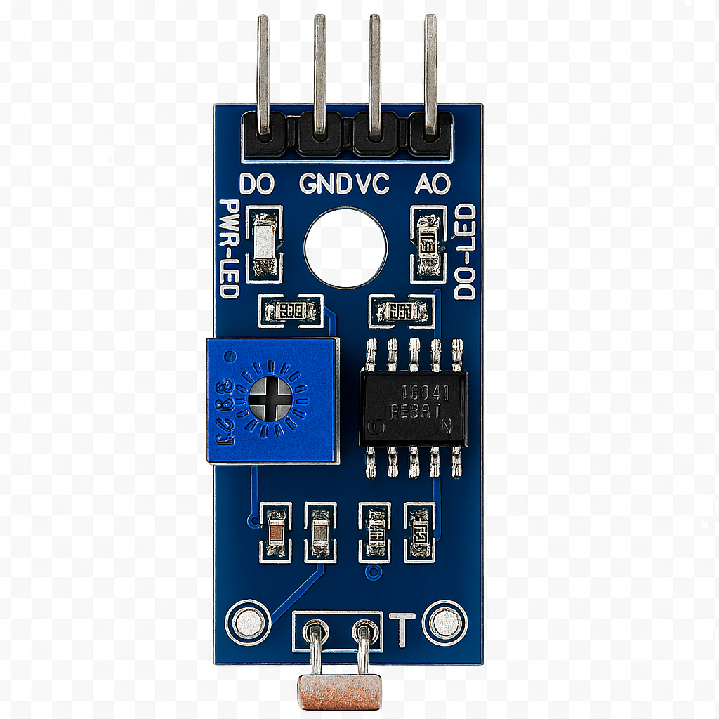
 Design with cảm biến in Cirkit Designer
Introduction
The cảm biến (sensor), manufactured by ASD with part ID QWE, is a versatile electronic component designed to detect physical properties such as temperature, light, or motion. It converts these physical phenomena into electrical signals for further processing in electronic systems. This sensor is widely used in various applications, including environmental monitoring, automation systems, robotics, and IoT devices.
Explore Projects Built with cảm biến
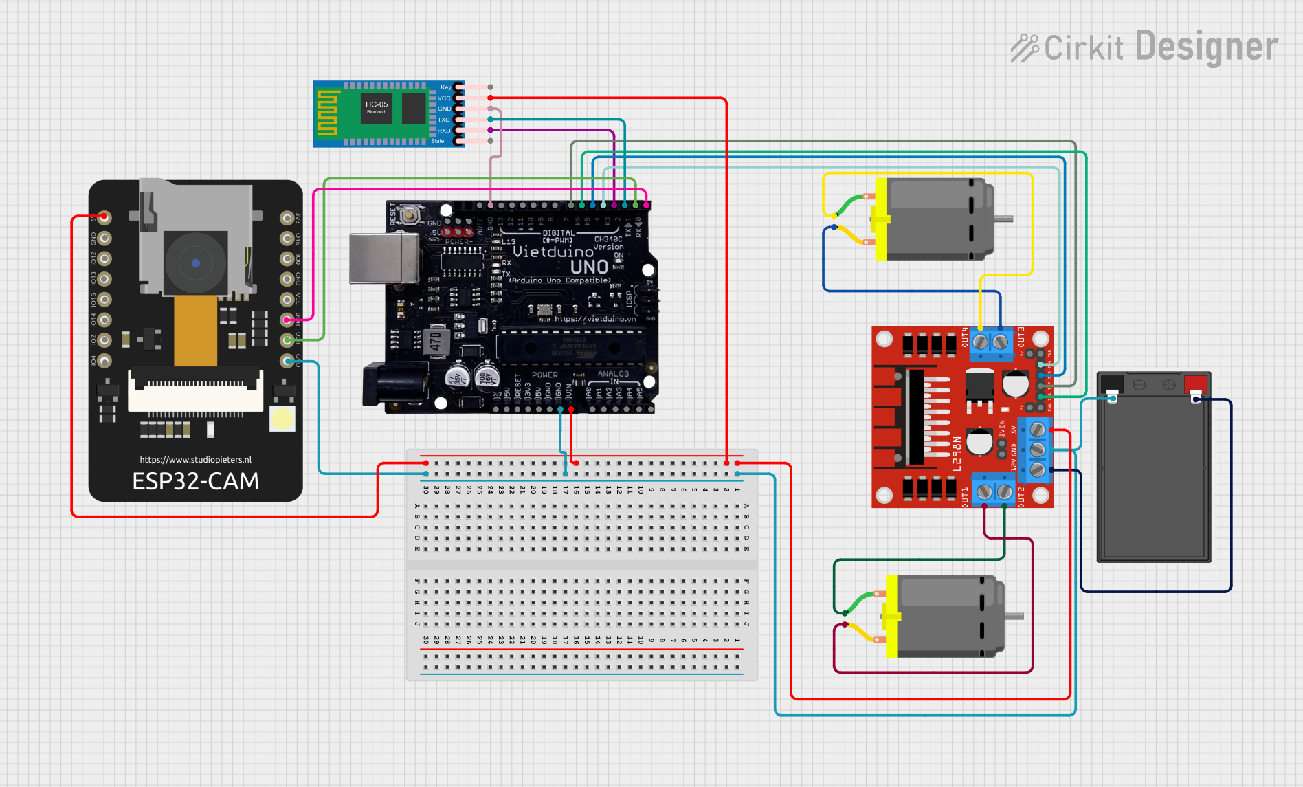 Open Project in Cirkit Designer
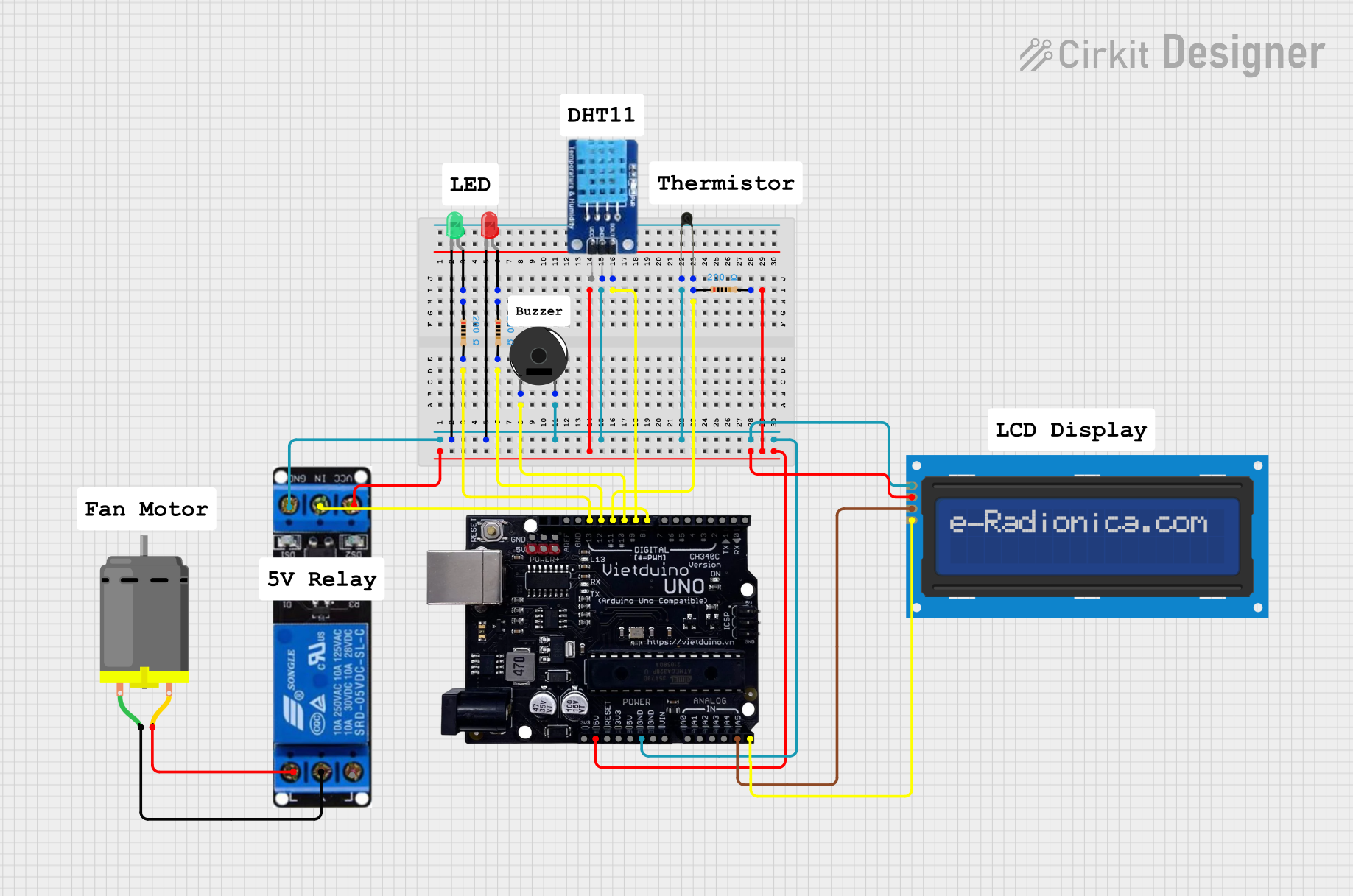 Open Project in Cirkit Designer
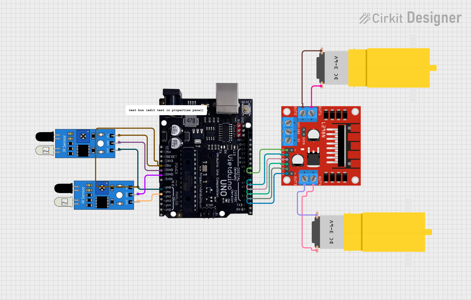 Open Project in Cirkit Designer
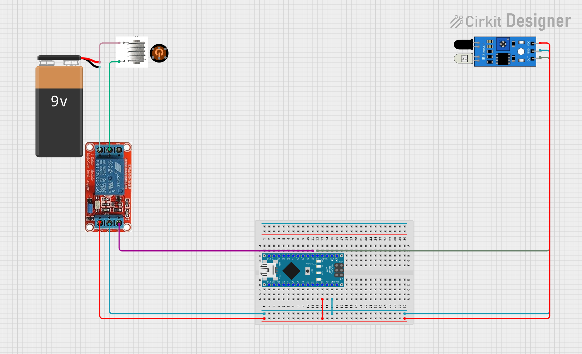 Open Project in Cirkit Designer
Explore Projects Built with cảm biến
Open Project in Cirkit DesignerOpen Project in Cirkit DesignerOpen Project in Cirkit DesignerOpen Project in Cirkit DesignerTechnical Specifications
Below are the key technical details and pin configuration for the cảm biến:
Key Technical Details
- Manufacturer: ASD
- Part ID: QWE
- Operating Voltage: 3.3V to 5V
- Output Signal: Analog or Digital (depending on the specific model)
- Detection Range: Varies based on the type of sensor (e.g., temperature: -40°C to 125°C, light: 0 to 100,000 lux)
- Power Consumption: Typically < 10mA
- Response Time: < 1ms (varies by sensor type)
- Operating Temperature: -40°C to 85°C
Pin Configuration and Descriptions
The cảm biến typically has three or more pins, depending on the specific model. Below is a general pinout:
| Pin | Name | Description |
|---|---|---|
| 1 | VCC | Power supply pin. Connect to 3.3V or 5V, depending on the sensor's requirements. |
| 2 | GND | Ground pin. Connect to the ground of the circuit. |
| 3 | OUT (Signal) | Output pin. Provides the sensor's signal (analog or digital). |
| 4 | Additional Pin | Optional pin for specific features (e.g., I2C/SPI communication, interrupt). |
Note: Refer to the specific datasheet for detailed pinout information if the cảm biến has additional features.
Usage Instructions
How to Use the Cảm Biến in a Circuit
- Power the Sensor: Connect the VCC pin to a 3.3V or 5V power source and the GND pin to the ground of your circuit.
- Connect the Output: Attach the OUT pin to an analog or digital input pin of your microcontroller, depending on the sensor's output type.
- Read the Signal: Use an ADC (Analog-to-Digital Converter) for analog sensors or directly read the digital signal for digital sensors.
- Optional Connections: If the sensor supports communication protocols like I2C or SPI, connect the appropriate pins (e.g., SDA, SCL for I2C) to your microcontroller.
Important Considerations and Best Practices
- Power Supply: Ensure the power supply voltage matches the sensor's requirements to avoid damage.
- Signal Noise: Use decoupling capacitors near the sensor to reduce noise in the signal.
- Placement: Position the sensor appropriately to ensure accurate detection (e.g., avoid obstructions for motion sensors).
- Calibration: Some sensors may require calibration for accurate readings. Follow the manufacturer's guidelines.
Example: Using the Cảm Biến with Arduino UNO
Below is an example of how to connect and read data from the cảm biến using an Arduino UNO:
Circuit Connections
- Connect the VCC pin of the cảm biến to the 5V pin on the Arduino.
- Connect the GND pin of the cảm biến to the GND pin on the Arduino.
- Connect the OUT pin of the cảm biến to the A0 pin on the Arduino (for analog output).
Arduino Code
// Define the analog pin connected to the cảm biến
const int sensorPin = A0;

void setup() {
  // Initialize serial communication for debugging
  Serial.begin(9600);
}

void loop() {
  // Read the analog value from the cảm biến
  int sensorValue = analogRead(sensorPin);

  // Convert the analog value to a voltage (assuming 5V reference)
  float voltage = sensorValue * (5.0 / 1023.0);

  // Print the sensor value and voltage to the Serial Monitor
  Serial.print("Sensor Value: ");
  Serial.print(sensorValue);
  Serial.print(" | Voltage: ");
  Serial.println(voltage);

  // Add a small delay for stability
  delay(500);
}
Note: Modify the code as needed for digital sensors or sensors with specific communication protocols.
Troubleshooting and FAQs
Common Issues and Solutions
No Output Signal
- Cause: Incorrect wiring or insufficient power supply.
- Solution: Double-check the connections and ensure the power supply voltage matches the sensor's requirements.
Inconsistent Readings
- Cause: Electrical noise or improper placement of the sensor.
- Solution: Use decoupling capacitors and ensure the sensor is placed in an appropriate environment.
Sensor Not Responding
- Cause: Faulty sensor or incorrect code.
- Solution: Test the sensor with a simple circuit and verify the code logic.
FAQs
Q: Can the cảm biến be used with a 3.3V microcontroller?
A: Yes, as long as the sensor's operating voltage range includes 3.3V.Q: How do I calibrate the cảm biến?
A: Refer to the manufacturer's datasheet for calibration instructions specific to your sensor model.Q: Can I use multiple cảm biến units in the same circuit?
A: Yes, but ensure each sensor has a unique address (if using I2C) or separate input pins for analog/digital signals.
This documentation provides a comprehensive guide to understanding and using the cảm biến effectively in your projects. For further details, consult the manufacturer's datasheet or technical support.