
How to Use VNH2SP30: Examples, Pinouts, and Specs
 Design with VNH2SP30 in Cirkit Designer
Introduction
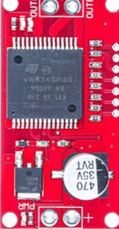
The VNH2SP30 is a high-current H-bridge motor driver designed to control DC motors and stepper motors. Manufactured by Arduino, this robust component is capable of handling high currents and features built-in protections such as overcurrent protection, thermal shutdown, and under-voltage lockout. These features make it an excellent choice for applications in robotics, automation, and motor control systems.
Explore Projects Built with VNH2SP30
 Open Project in Cirkit Designer
 Open Project in Cirkit Designer
 Open Project in Cirkit Designer
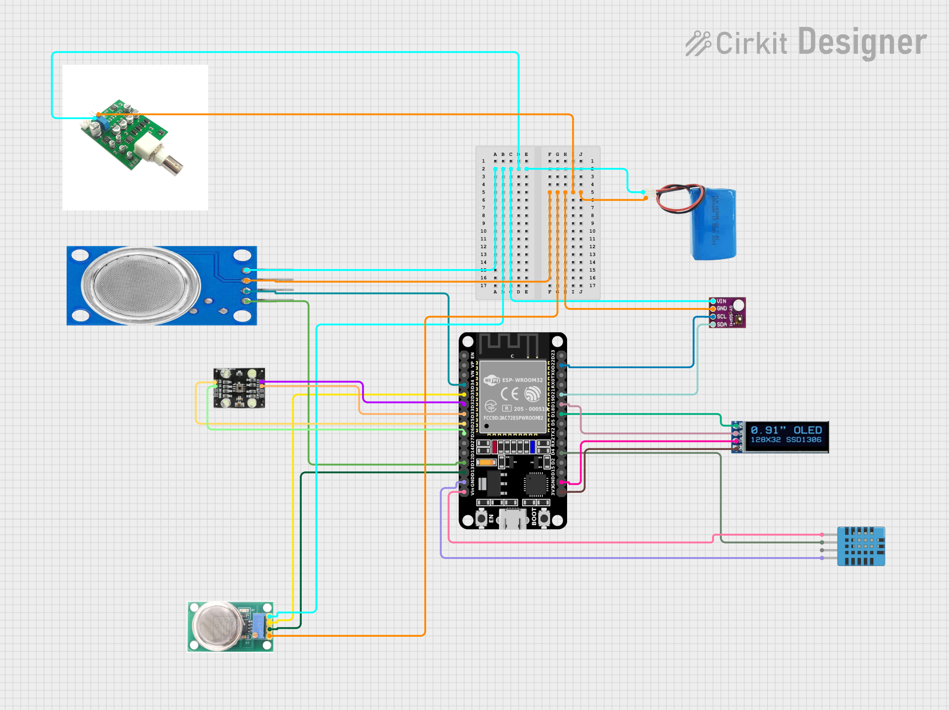
 Open Project in Cirkit Designer
Explore Projects Built with VNH2SP30

 Open Project in Cirkit Designer
 Open Project in Cirkit Designer
 Open Project in Cirkit Designer
 Open Project in Cirkit Designer
Common Applications
- Robotics: Driving motors for robotic arms, wheels, or tracks.
- Automation: Controlling conveyor belts or automated systems.
- Remote-controlled vehicles: Powering motors for cars, boats, or drones.
- Industrial equipment: Operating stepper motors in precision machinery.
Technical Specifications
The VNH2SP30 is a versatile motor driver with the following key specifications:
| Parameter | Value |
|---|---|
| Operating Voltage Range | 5.5V to 16V |
| Maximum Output Current | 30A (continuous) |
| Peak Output Current | 60A (for short durations) |
| Logic Input Voltage Range | 0V to 5V |
| PWM Frequency | Up to 20 kHz |
| Thermal Shutdown | Yes |
| Overcurrent Protection | Yes |
| Under-voltage Lockout | Yes |
| Package Type | Multiwatt15 (15-pin package) |
Pin Configuration and Descriptions
The VNH2SP30 has 15 pins, each serving a specific function. Below is the pinout and description:
| Pin Number | Pin Name | Description |
|---|---|---|
| 1 | INA | Input A: Controls the direction of the motor (logic level input). |
| 2 | INB | Input B: Controls the direction of the motor (logic level input). |
| 3 | ENA | Enable A: Enables the H-bridge for motor operation (logic level input). |
| 4 | ENB | Enable B: Enables the H-bridge for motor operation (logic level input). |
| 5 | PWM | PWM Input: Controls motor speed via pulse-width modulation. |
| 6 | CS | Current Sense: Outputs a voltage proportional to the motor current. |
| 7 | GND | Ground: Connect to the system ground. |
| 8 | OUTA | Output A: Connect to one terminal of the motor. |
| 9 | OUTB | Output B: Connect to the other terminal of the motor. |
| 10 | VCC | Supply Voltage: Connect to the motor power supply (5.5V to 16V). |
| 11 | DIAG/EN | Diagnostic/Enable: Provides fault diagnostics and enables the driver. |
| 12-15 | NC | Not Connected: These pins are not used. |
Usage Instructions
How to Use the VNH2SP30 in a Circuit
- Power Supply: Connect the VCC pin to a power supply (5.5V to 16V) capable of providing sufficient current for your motor. Connect the GND pin to the system ground.
- Motor Connections: Connect the motor terminals to the OUTA and OUTB pins.
- Logic Inputs: Use INA and INB to control the motor's direction. Apply a PWM signal to the PWM pin to control the motor speed.
- Enable Pins: Set ENA and ENB to a high logic level to enable the H-bridge.
- Current Monitoring: Optionally, connect the CS pin to an analog input on a microcontroller to monitor the motor current.
- Fault Detection: Use the DIAG/EN pin to detect faults such as overcurrent or thermal shutdown.
Important Considerations
- Ensure the power supply can handle the motor's current requirements, including peak currents.
- Use appropriate heat sinks or cooling mechanisms to prevent overheating during high-current operation.
- Avoid exceeding the maximum voltage and current ratings to prevent damage to the component.
- Use decoupling capacitors near the VCC pin to reduce noise and voltage spikes.
Example: Connecting the VNH2SP30 to an Arduino UNO
Below is an example of how to control a DC motor using the VNH2SP30 and an Arduino UNO:
Circuit Connections
- Connect the VNH2SP30's VCC to a 12V power supply and GND to the Arduino's GND.
- Connect OUTA and OUTB to the motor terminals.
- Connect INA, INB, and PWM to Arduino digital pins 7, 8, and 9, respectively.
- Connect ENA and ENB to 5V (logic high) to enable the H-bridge.
Arduino Code
// Define pin connections
const int INA = 7;  // Input A for motor direction
const int INB = 8;  // Input B for motor direction
const int PWM = 9;  // PWM pin for motor speed control

void setup() {
  // Set pin modes
  pinMode(INA, OUTPUT);
  pinMode(INB, OUTPUT);
  pinMode(PWM, OUTPUT);
}

void loop() {
  // Rotate motor forward
  digitalWrite(INA, HIGH);  // Set direction to forward
  digitalWrite(INB, LOW);
  analogWrite(PWM, 128);    // Set speed to 50% (128 out of 255)
  delay(2000);              // Run for 2 seconds

  // Rotate motor backward
  digitalWrite(INA, LOW);   // Set direction to backward
  digitalWrite(INB, HIGH);
  analogWrite(PWM, 128);    // Set speed to 50%
  delay(2000);              // Run for 2 seconds

  // Stop motor
  digitalWrite(INA, LOW);
  digitalWrite(INB, LOW);
  analogWrite(PWM, 0);      // Set speed to 0
  delay(2000);              // Stop for 2 seconds
}
Troubleshooting and FAQs
Common Issues and Solutions
Motor Not Spinning
- Cause: Incorrect wiring or logic inputs.
- Solution: Double-check the connections and ensure INA, INB, and PWM are receiving the correct signals.
Overheating
- Cause: Excessive current draw or insufficient cooling.
- Solution: Use a heat sink or fan to dissipate heat. Ensure the motor's current is within the VNH2SP30's limits.
No Response from the Driver
- Cause: Fault condition triggered (e.g., overcurrent or thermal shutdown).
- Solution: Check the DIAG/EN pin for fault diagnostics. Allow the driver to cool down if thermal shutdown occurred.
PWM Signal Not Working
- Cause: Incorrect PWM frequency or duty cycle.
- Solution: Ensure the PWM frequency is within the supported range (up to 20 kHz) and the duty cycle is set correctly.
FAQs
Can the VNH2SP30 drive stepper motors? Yes, it can drive stepper motors by controlling the coils with appropriate logic signals.
What is the purpose of the CS pin? The CS pin provides a voltage proportional to the motor current, which can be used for current monitoring or feedback.
Is the VNH2SP30 compatible with 3.3V logic? No, the logic inputs require 5V signals. Use a level shifter if interfacing with a 3.3V microcontroller.
How do I reset the driver after a fault? Toggle the DIAG/EN pin or cycle the power to reset the driver.