How to Use USB 2.0 Female Module: Examples, Pinouts, and Specs
Introduction
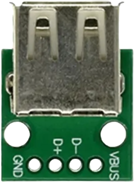
The USB 2.0 Female Module is a connector designed to interface USB devices with a host system, such as a computer, microcontroller, or development board. It supports data transfer and power supply capabilities, making it a versatile component for a wide range of electronic projects. This module is commonly used in applications such as USB device prototyping, power delivery, and communication between peripherals and host systems.
Explore Projects Built with USB 2.0 Female Module


Explore Projects Built with USB 2.0 Female Module
Common Applications
- Connecting USB devices (e.g., flash drives, keyboards, mice) to a host system.
- Prototyping USB-based circuits and projects.
- Powering small electronic devices via USB.
- Enabling communication between microcontrollers and USB peripherals.
Technical Specifications
The USB 2.0 Female Module adheres to the USB 2.0 standard, ensuring compatibility with most USB devices and hosts. Below are the key technical details:
General Specifications
- Standard: USB 2.0
- Data Transfer Rate: Up to 480 Mbps (High Speed)
- Voltage Rating: 5V DC
- Current Rating: Up to 500 mA (standard USB 2.0 power output)
- Connector Type: USB Type-A Female
- Operating Temperature: -20°C to 70°C
Pin Configuration
The USB 2.0 Female Module has four pins, each with a specific function. The table below describes the pin configuration:
| Pin Number | Name | Description |
|---|---|---|
| 1 | VCC | +5V power supply |
| 2 | D- | Data line (negative) |
| 3 | D+ | Data line (positive) |
| 4 | GND | Ground connection |
Usage Instructions
How to Use the USB 2.0 Female Module in a Circuit
- Power Supply: Connect the VCC pin to a 5V power source and the GND pin to the ground of your circuit.
- Data Lines: Connect the D+ and D- pins to the corresponding data lines of your microcontroller or USB host.
- Mounting: Secure the module to your PCB or breadboard using soldering or a compatible connector.
- Device Connection: Plug in the USB device into the female connector to establish a connection.
Important Considerations
- Ensure the power supply does not exceed 5V to avoid damaging the module or connected devices.
- Use proper shielding and grounding to minimize noise on the data lines.
- For data communication, ensure the microcontroller or host supports USB protocols.
- Avoid exceeding the 500 mA current limit unless the host system supports higher power delivery.
Example: Connecting to an Arduino UNO
The USB 2.0 Female Module can be used to interface USB devices with an Arduino UNO. Below is an example of how to connect the module and read data from a USB device.
Circuit Connections
- Connect the VCC pin of the module to the 5V pin on the Arduino.
- Connect the GND pin of the module to the GND pin on the Arduino.
- Connect the D+ and D- pins to the appropriate data pins on the Arduino (e.g., digital pins 2 and 3).
Sample Code
#include <SoftwareSerial.h>

// Define pins for USB data lines
#define USB_D_PLUS 2  // D+ connected to digital pin 2
#define USB_D_MINUS 3 // D- connected to digital pin 3

SoftwareSerial usbSerial(USB_D_PLUS, USB_D_MINUS); // Initialize software serial

void setup() {
  Serial.begin(9600); // Start serial communication with the computer
  usbSerial.begin(9600); // Start communication with the USB device

  Serial.println("USB 2.0 Female Module Test");
}

void loop() {
  // Check if data is available from the USB device
  if (usbSerial.available()) {
    char data = usbSerial.read(); // Read a byte of data
    Serial.print("Received: ");
    Serial.println(data); // Print the received data to the Serial Monitor
  }
}
Note: The above code assumes the use of a USB-to-serial converter or a compatible USB device. Direct USB communication may require additional libraries or hardware.
Troubleshooting and FAQs
Common Issues
No Power to the USB Device
- Cause: Incorrect connection of the VCC or GND pins.
- Solution: Verify the power supply connections and ensure the voltage is 5V.
Data Transfer Fails
- Cause: Improper connection of the D+ and D- pins or noise on the data lines.
- Solution: Check the data line connections and use shielded cables if necessary.
Device Not Recognized
- Cause: Incompatible USB device or missing drivers on the host system.
- Solution: Ensure the device is compatible with USB 2.0 and install the required drivers.
Overheating
- Cause: Excessive current draw by the connected device.
- Solution: Ensure the device does not exceed the 500 mA current limit.
FAQs
Can this module be used with USB 3.0 devices? Yes, USB 3.0 devices are backward compatible with USB 2.0, but the data transfer rate will be limited to 480 Mbps.
Is additional circuitry required for data communication? For basic communication, no additional circuitry is needed. However, advanced USB protocols may require a USB host controller or library.
Can this module supply power to multiple devices? It is not recommended to power multiple devices directly from this module unless the total current draw is within the 500 mA limit. Use a powered USB hub for higher power requirements.