How to Use Matrix Keypad 5x4 Membrane: Examples, Pinouts, and Specs
Introduction
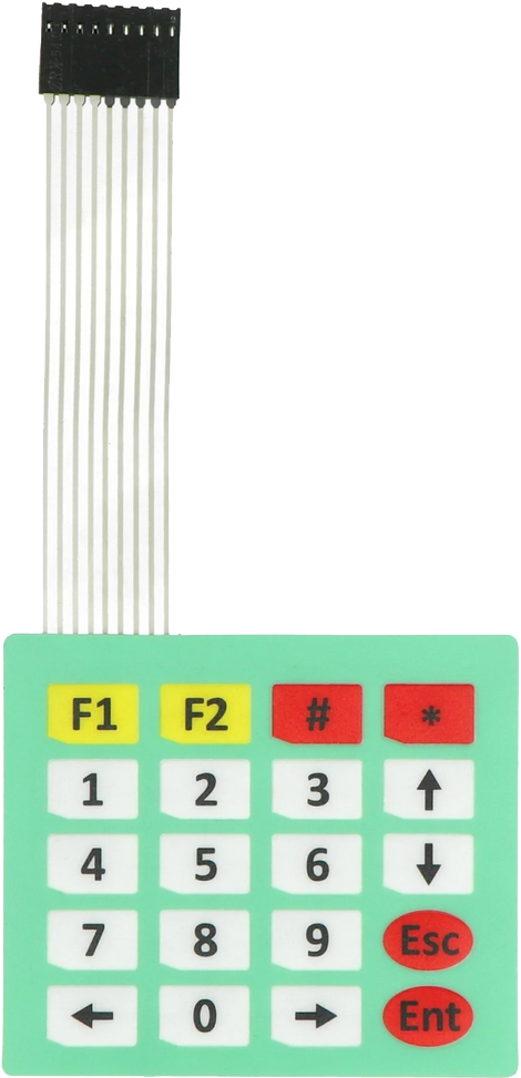
The Matrix Keypad 5x4 Membrane is a compact and lightweight input device featuring 20 keys arranged in a 5-row by 4-column grid. It is designed for efficient input of numerical and alphanumeric data. The membrane design ensures a thin, flexible, and durable structure, making it ideal for applications where space is limited. Each key press is detected by identifying the intersection of the corresponding row and column, enabling simple and reliable operation.
Explore Projects Built with Matrix Keypad 5x4 Membrane


Explore Projects Built with Matrix Keypad 5x4 Membrane
Common Applications and Use Cases
- Embedded systems requiring user input
- Security systems (e.g., PIN entry for locks)
- Home automation control panels
- Calculator-style input devices
- Industrial equipment interfaces
- Prototyping and educational projects
Technical Specifications
Below are the key technical details of the Matrix Keypad 5x4 Membrane:
| Parameter | Value |
|---|---|
| Number of Keys | 20 |
| Rows | 5 |
| Columns | 4 |
| Operating Voltage | 3.3V to 5V |
| Interface Type | Matrix (row-column scanning) |
| Dimensions | ~77mm x 69mm |
| Connector Type | 8-pin ribbon cable |
| Keypad Material | Flexible membrane |
| Lifespan | ~1,000,000 key presses |
Pin Configuration and Descriptions
The Matrix Keypad 5x4 Membrane uses an 8-pin ribbon cable for interfacing. The pins correspond to the rows and columns of the keypad.
| Pin Number | Label | Description |
|---|---|---|
| 1 | R1 | Row 1 |
| 2 | R2 | Row 2 |
| 3 | R3 | Row 3 |
| 4 | R4 | Row 4 |
| 5 | R5 | Row 5 |
| 6 | C1 | Column 1 |
| 7 | C2 | Column 2 |
| 8 | C3 | Column 3 |
| 9 | C4 | Column 4 |
Usage Instructions
How to Use the Component in a Circuit
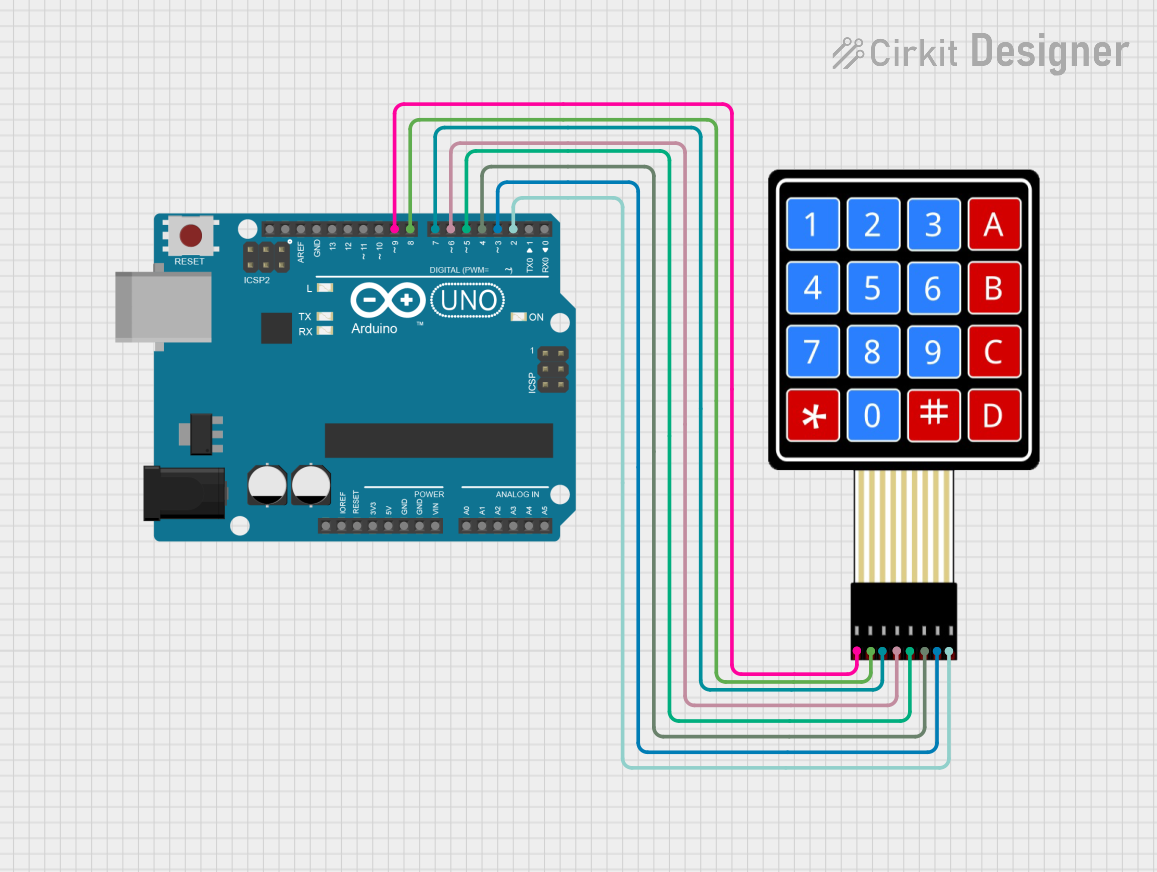
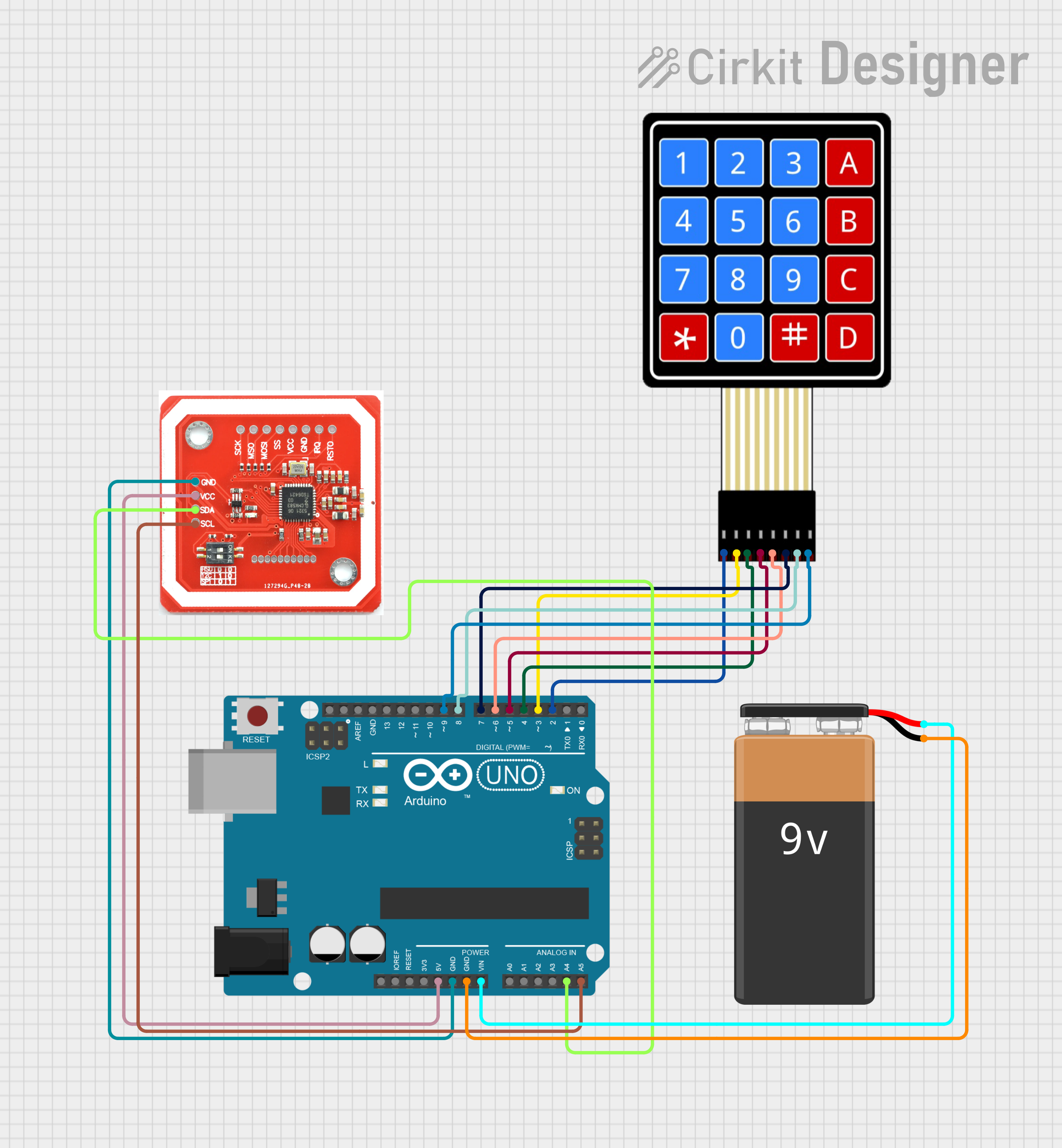
Connect the Keypad to a Microcontroller:
- Use the 8-pin ribbon cable to connect the keypad to the microcontroller.
- Assign the row pins (R1 to R5) and column pins (C1 to C4) to digital I/O pins on the microcontroller.
Scan the Keypad:
- To detect a key press, the microcontroller sends signals to the row pins and reads the column pins.
- When a key is pressed, the corresponding row and column pins are shorted, allowing the microcontroller to identify the pressed key.
Debounce the Keys:
- Implement software or hardware debouncing to avoid false key presses caused by mechanical bouncing.
Power Requirements:
- Ensure the keypad operates within the specified voltage range (3.3V to 5V).
Important Considerations and Best Practices
- Pull-Up Resistors: Use internal or external pull-up resistors on the column pins to ensure stable readings.
- Avoid Excessive Force: Do not press the keys with excessive force to maintain the keypad's lifespan.
- Environmental Protection: Protect the keypad from moisture and dust to ensure reliable operation.
- Testing: Test the keypad with a multimeter or microcontroller to verify proper functionality before integrating it into your project.
Example Code for Arduino UNO
Below is an example of how to use the Matrix Keypad 5x4 Membrane with an Arduino UNO. This code uses the Keypad library to simplify the scanning process.
#include <Keypad.h>

// Define the number of rows and columns on the keypad
const byte ROWS = 5; // Five rows
const byte COLS = 4; // Four columns

// Define the keymap for the keypad
char keys[ROWS][COLS] = {
  {'1', '2', '3', 'A'},
  {'4', '5', '6', 'B'},
  {'7', '8', '9', 'C'},
  {'*', '0', '#', 'D'},
  {'E', 'F', 'G', 'H'}
};

// Define the row and column pins connected to the Arduino
byte rowPins[ROWS] = {9, 8, 7, 6, 5}; // Connect to R1, R2, R3, R4, R5
byte colPins[COLS] = {4, 3, 2, 1};    // Connect to C1, C2, C3, C4

// Create a Keypad object
Keypad keypad = Keypad(makeKeymap(keys), rowPins, colPins, ROWS, COLS);

void setup() {
  Serial.begin(9600); // Initialize serial communication
  Serial.println("Matrix Keypad 5x4 Test");
}

void loop() {
  char key = keypad.getKey(); // Get the key pressed

  if (key) {
    // If a key is pressed, print it to the Serial Monitor
    Serial.print("Key Pressed: ");
    Serial.println(key);
  }
}
Notes:
- Install the
Keypadlibrary in the Arduino IDE before uploading the code. - Adjust the
rowPinsandcolPinsarrays to match your wiring.
Troubleshooting and FAQs
Common Issues and Solutions
No Key Press Detected:
- Verify the connections between the keypad and the microcontroller.
- Ensure the microcontroller pins are configured as inputs for the column pins.
Incorrect Key Press Detected:
- Check the keymap in the code to ensure it matches the physical layout of the keypad.
- Verify that the row and column pins are connected to the correct microcontroller pins.
Multiple Keys Detected Simultaneously:
- Implement proper debouncing in the code to avoid false readings.
- Ensure no conductive material is shorting the keypad pins.
Keypad Not Responding:
- Confirm the operating voltage is within the specified range (3.3V to 5V).
- Test the keypad with a multimeter to check for continuity between rows and columns when a key is pressed.
FAQs
Q: Can I use this keypad with a Raspberry Pi?
A: Yes, the keypad can be used with a Raspberry Pi. You will need to write a Python script to scan the rows and columns, or use a library like gpiozero for easier implementation.
Q: How do I clean the keypad?
A: Use a soft, dry cloth to clean the surface. Avoid using water or cleaning agents that may damage the membrane.
Q: Can I extend the ribbon cable?
A: Yes, but ensure the extended cable does not introduce significant resistance or noise, which could affect performance.
Q: Is the keypad waterproof?
A: No, the keypad is not waterproof. Use it in a dry environment or consider additional protective measures.