Cirkit Designer Logo
Cirkit Designer
Your all-in-one circuit design IDE
Home / 
Component Documentation

How to Use HW-532: Examples, Pinouts, and Specs

Image of HW-532
Cirkit Designer LogoDesign with HW-532 in Cirkit Designer

Introduction

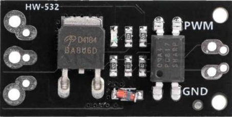
The HW-532 is a versatile electronic component widely used in signal processing, control systems, and other electronic applications. Its compact design ensures easy integration into circuit boards, making it a popular choice for engineers and hobbyists alike. Known for its reliability and efficiency, the HW-532 is ideal for projects requiring consistent performance and durability.

Explore Projects Built with HW-532

Use Cirkit Designer to design, explore, and prototype these projects online. Some projects support real-time simulation. Click "Open Project" to start designing instantly!
Battery-Powered nRF52840 and HT-RA62 Communication Module
Image of NRF52840+HT-RA62: A project utilizing HW-532 in a practical application
This circuit is a wireless communication system powered by a 18650 Li-ion battery, featuring an nRF52840 ProMicro microcontroller and an HT-RA62 transceiver module. The nRF52840 handles the control logic and interfaces with the HT-RA62 for data transmission, while the battery provides the necessary power for the entire setup.
Cirkit Designer LogoOpen Project in Cirkit Designer
Arduino UNO-Based Smart Irrigation System with Motion Detection and Bluetooth Connectivity
Image of Copy of wiring TA: A project utilizing HW-532 in a practical application
This circuit is a microcontroller-based control and monitoring system. It uses an Arduino UNO to read from a DHT22 temperature and humidity sensor and an HC-SR501 motion sensor, display data on an LCD, and control a water pump and an LED through a relay. The HC-05 Bluetooth module allows for wireless communication.
Cirkit Designer LogoOpen Project in Cirkit Designer
Smart Weighing System with ESP8266 and HX711 - Battery Powered and Wi-Fi Enabled
Image of gggg: A project utilizing HW-532 in a practical application
This circuit is a multi-sensor data acquisition system powered by a 18650 battery and managed by an ESP8266 microcontroller. It includes a load sensor interfaced with an HX711 module for weight measurement, an IR sensor, an ADXL345 accelerometer, a VL53L0X distance sensor, and a Neo 6M GPS module for location tracking. The system is designed for wireless data transmission and is supported by a TP4056 module for battery charging.
Cirkit Designer LogoOpen Project in Cirkit Designer
Arduino Mega 2560 Based Security System with Fingerprint Authentication and SMS Alerts
Image of Door security system: A project utilizing HW-532 in a practical application
This circuit features an Arduino Mega 2560 microcontroller interfaced with a SIM800L GSM module, two fingerprint scanners, an I2C LCD display, an IR sensor, and a piezo buzzer. Power management is handled by a PowerBoost 1000 Basic Pad USB, a TP4056 charging module, and a Li-ion 18650 battery, with an option to use a Mini AC-DC 110V-230V to 5V 700mA module for direct power supply. The primary functionality appears to be a security system with GSM communication capabilities, biometric access control, and visual/audible feedback.
Cirkit Designer LogoOpen Project in Cirkit Designer

Explore Projects Built with HW-532

Use Cirkit Designer to design, explore, and prototype these projects online. Some projects support real-time simulation. Click "Open Project" to start designing instantly!
Image of NRF52840+HT-RA62: A project utilizing HW-532 in a practical application
Battery-Powered nRF52840 and HT-RA62 Communication Module
This circuit is a wireless communication system powered by a 18650 Li-ion battery, featuring an nRF52840 ProMicro microcontroller and an HT-RA62 transceiver module. The nRF52840 handles the control logic and interfaces with the HT-RA62 for data transmission, while the battery provides the necessary power for the entire setup.
Cirkit Designer LogoOpen Project in Cirkit Designer
Image of Copy of wiring TA: A project utilizing HW-532 in a practical application
Arduino UNO-Based Smart Irrigation System with Motion Detection and Bluetooth Connectivity
This circuit is a microcontroller-based control and monitoring system. It uses an Arduino UNO to read from a DHT22 temperature and humidity sensor and an HC-SR501 motion sensor, display data on an LCD, and control a water pump and an LED through a relay. The HC-05 Bluetooth module allows for wireless communication.
Cirkit Designer LogoOpen Project in Cirkit Designer
Image of gggg: A project utilizing HW-532 in a practical application
Smart Weighing System with ESP8266 and HX711 - Battery Powered and Wi-Fi Enabled
This circuit is a multi-sensor data acquisition system powered by a 18650 battery and managed by an ESP8266 microcontroller. It includes a load sensor interfaced with an HX711 module for weight measurement, an IR sensor, an ADXL345 accelerometer, a VL53L0X distance sensor, and a Neo 6M GPS module for location tracking. The system is designed for wireless data transmission and is supported by a TP4056 module for battery charging.
Cirkit Designer LogoOpen Project in Cirkit Designer
Image of Door security system: A project utilizing HW-532 in a practical application
Arduino Mega 2560 Based Security System with Fingerprint Authentication and SMS Alerts
This circuit features an Arduino Mega 2560 microcontroller interfaced with a SIM800L GSM module, two fingerprint scanners, an I2C LCD display, an IR sensor, and a piezo buzzer. Power management is handled by a PowerBoost 1000 Basic Pad USB, a TP4056 charging module, and a Li-ion 18650 battery, with an option to use a Mini AC-DC 110V-230V to 5V 700mA module for direct power supply. The primary functionality appears to be a security system with GSM communication capabilities, biometric access control, and visual/audible feedback.
Cirkit Designer LogoOpen Project in Cirkit Designer

Common Applications and Use Cases

  • Signal amplification and processing
  • Control systems in automation
  • Audio and communication circuits
  • Embedded systems and IoT devices
  • General-purpose electronic projects

Technical Specifications

The HW-532 is designed to deliver reliable performance under a range of operating conditions. Below are its key technical specifications:

Parameter Value
Operating Voltage 3.3V to 5V
Maximum Current 50mA
Power Consumption < 250mW
Operating Temperature -40°C to +85°C
Dimensions 25mm x 15mm x 5mm
Communication Protocol I2C or SPI (depending on configuration)

Pin Configuration and Descriptions

The HW-532 features a standard pinout for easy integration. Below is the pin configuration:

Pin Number Pin Name Description
1 VCC Power supply input (3.3V to 5V)
2 GND Ground connection
3 SDA Data line for I2C communication
4 SCL Clock line for I2C communication
5 CS Chip Select for SPI communication (optional)
6 INT Interrupt output for signaling events (optional)

Usage Instructions

The HW-532 is straightforward to use in a variety of circuits. Below are the steps and best practices for integrating it into your project:

How to Use the HW-532 in a Circuit

  1. Power Supply: Connect the VCC pin to a 3.3V or 5V power source and the GND pin to the ground.
  2. Communication Setup:
    • For I2C: Connect the SDA and SCL pins to the corresponding I2C pins on your microcontroller.
    • For SPI: Use the CS pin along with the SPI MOSI, MISO, and SCK lines (not shown in the pinout above).
  3. Interrupts (Optional): If your application requires event signaling, connect the INT pin to a GPIO pin on your microcontroller.
  4. Pull-Up Resistors: For I2C communication, ensure that SDA and SCL lines have appropriate pull-up resistors (typically 4.7kΩ).

Important Considerations and Best Practices

  • Voltage Compatibility: Ensure the HW-532's operating voltage matches your circuit's power supply.
  • Signal Integrity: Use short and well-routed connections for SDA, SCL, and other signal lines to minimize noise.
  • Heat Dissipation: While the HW-532 is efficient, ensure adequate ventilation if used in high-temperature environments.
  • Testing: Test the component in a breadboard setup before soldering it onto a PCB.

Example: Using HW-532 with Arduino UNO

Below is an example of how to use the HW-532 with an Arduino UNO via I2C communication:

#include <Wire.h> // Include the Wire library for I2C communication

#define HW532_ADDRESS 0x40 // Replace with the actual I2C address of HW-532

void setup() {
  Wire.begin(); // Initialize I2C communication
  Serial.begin(9600); // Start serial communication for debugging

  // Send initialization command to HW-532
  Wire.beginTransmission(HW532_ADDRESS);
  Wire.write(0x01); // Example command to initialize the HW-532
  Wire.endTransmission();

  Serial.println("HW-532 initialized successfully.");
}

void loop() {
  // Request data from HW-532
  Wire.requestFrom(HW532_ADDRESS, 2); // Request 2 bytes of data

  if (Wire.available() == 2) {
    int data = Wire.read() << 8 | Wire.read(); // Combine two bytes into one value
    Serial.print("HW-532 Data: ");
    Serial.println(data); // Print the received data
  }

  delay(1000); // Wait for 1 second before the next request
}

Troubleshooting and FAQs

Common Issues and Solutions

  1. No Response from HW-532:

    • Cause: Incorrect wiring or power supply.
    • Solution: Double-check all connections and ensure the power supply voltage is within the specified range.
  2. I2C Communication Fails:

    • Cause: Missing or incorrect pull-up resistors on SDA and SCL lines.
    • Solution: Add 4.7kΩ pull-up resistors to SDA and SCL.
  3. Overheating:

    • Cause: Excessive current draw or high ambient temperature.
    • Solution: Verify the current draw and ensure proper ventilation.
  4. Incorrect Data Output:

    • Cause: Mismatched I2C address or incorrect initialization.
    • Solution: Verify the I2C address and ensure the initialization sequence is correct.

FAQs

Q1: Can the HW-532 operate at 3.3V?
A1: Yes, the HW-532 is compatible with both 3.3V and 5V power supplies.

Q2: Is the HW-532 compatible with SPI communication?
A2: Yes, the HW-532 supports SPI communication if the CS pin is used.

Q3: Do I need external components to use the HW-532?
A3: For I2C communication, you may need pull-up resistors on the SDA and SCL lines. Other components depend on your specific application.

Q4: What is the maximum data rate for I2C communication?
A4: The HW-532 supports standard I2C speeds up to 400kHz.

By following this documentation, you can effectively integrate and troubleshoot the HW-532 in your projects.