Cirkit Designer Logo
Cirkit Designer
Your all-in-one circuit design IDE
Home / 
Component Documentation

How to Use 5 EXAR RS232 to TTL Module Dual Channel: Examples, Pinouts, and Specs

Image of 5 EXAR RS232 to TTL Module Dual Channel
Cirkit Designer LogoDesign with 5 EXAR RS232 to TTL Module Dual Channel in Cirkit Designer

Introduction

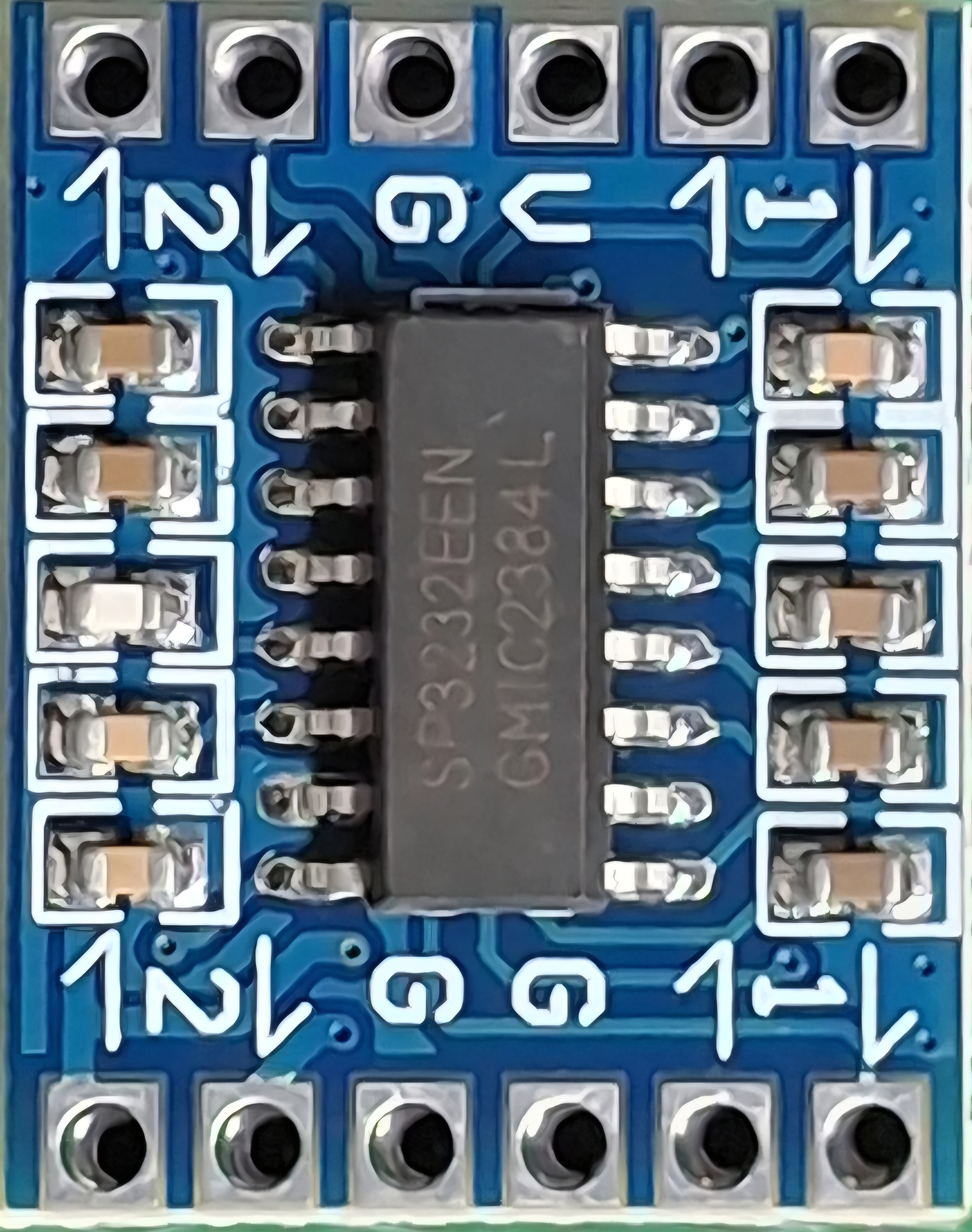
The EXAR RS232 to TTL Module Dual Channel is a versatile interface module designed to convert RS232 signals to TTL voltage levels. This module enables seamless communication between devices that operate on different voltage standards, such as microcontrollers, computers, and other serial communication devices. With its dual-channel capability, it supports bidirectional communication on two independent data lines, making it ideal for applications requiring multiple serial connections.

Explore Projects Built with 5 EXAR RS232 to TTL Module Dual Channel

Use Cirkit Designer to design, explore, and prototype these projects online. Some projects support real-time simulation. Click "Open Project" to start designing instantly!
Arduino UNO and Relay-Controlled RS485 Communication System
Image of Diagrama: A project utilizing 5 EXAR RS232 to TTL Module Dual Channel in a practical application
This circuit features an Arduino UNO microcontroller interfaced with a 4-channel relay module and a UART TTL to RS485 converter. The Arduino controls the relays via digital pins and communicates with the RS485 converter for serial communication, enabling control of external devices and communication over long distances.
Cirkit Designer LogoOpen Project in Cirkit Designer
DC-DC Converter and Relay Module Power Distribution System
Image of relay: A project utilizing 5 EXAR RS232 to TTL Module Dual Channel in a practical application
This circuit consists of a DC-DC converter powering a 6-channel power module, which in turn supplies 5V to a 2-relay module. The power module distributes the converted voltage to the relay module, enabling it to control external devices.
Cirkit Designer LogoOpen Project in Cirkit Designer
STM32 and Arduino UNO Based Dual RS485 Communication Interface
Image of STM to Arduino RS485: A project utilizing 5 EXAR RS232 to TTL Module Dual Channel in a practical application
This circuit consists of two microcontrollers, an STM32F103C8T6 and an Arduino UNO, each interfaced with separate RS485 transceiver modules for serial communication. The STM32F103C8T6 controls the RE (Receiver Enable) and DE (Driver Enable) pins of one RS485 module to manage its operation, and communicates via the A9 and A10 pins for DI (Data Input) and RO (Receiver Output), respectively. The Arduino UNO is similarly connected to another RS485 module, with digital pins D2 and D3 interfacing with DI and RO, and D8 controlling both RE and DE. The RS485 modules are connected to each other through their A and B differential communication lines, enabling serial data exchange between the two microcontrollers over a robust and long-distance capable RS485 network.
Cirkit Designer LogoOpen Project in Cirkit Designer
ESP8266 NodeMCU with LoRa and RS-485 Communication and Ethernet Connectivity
Image of Wiring Diagram LoRa: A project utilizing 5 EXAR RS232 to TTL Module Dual Channel in a practical application
This circuit serves as a multi-protocol communication hub featuring two ESP8266 NodeMCUs for processing, each connected to a LoRa Ra-02 SX1278 for long-range wireless communication. One NodeMCU is also connected to an RS-485 module for serial communication and a W5500 Ethernet module for network connectivity, with MB102 modules supplying power.
Cirkit Designer LogoOpen Project in Cirkit Designer

Explore Projects Built with 5 EXAR RS232 to TTL Module Dual Channel

Use Cirkit Designer to design, explore, and prototype these projects online. Some projects support real-time simulation. Click "Open Project" to start designing instantly!
Image of Diagrama: A project utilizing 5 EXAR RS232 to TTL Module Dual Channel in a practical application
Arduino UNO and Relay-Controlled RS485 Communication System
This circuit features an Arduino UNO microcontroller interfaced with a 4-channel relay module and a UART TTL to RS485 converter. The Arduino controls the relays via digital pins and communicates with the RS485 converter for serial communication, enabling control of external devices and communication over long distances.
Cirkit Designer LogoOpen Project in Cirkit Designer
Image of relay: A project utilizing 5 EXAR RS232 to TTL Module Dual Channel in a practical application
DC-DC Converter and Relay Module Power Distribution System
This circuit consists of a DC-DC converter powering a 6-channel power module, which in turn supplies 5V to a 2-relay module. The power module distributes the converted voltage to the relay module, enabling it to control external devices.
Cirkit Designer LogoOpen Project in Cirkit Designer
Image of STM to Arduino RS485: A project utilizing 5 EXAR RS232 to TTL Module Dual Channel in a practical application
STM32 and Arduino UNO Based Dual RS485 Communication Interface
This circuit consists of two microcontrollers, an STM32F103C8T6 and an Arduino UNO, each interfaced with separate RS485 transceiver modules for serial communication. The STM32F103C8T6 controls the RE (Receiver Enable) and DE (Driver Enable) pins of one RS485 module to manage its operation, and communicates via the A9 and A10 pins for DI (Data Input) and RO (Receiver Output), respectively. The Arduino UNO is similarly connected to another RS485 module, with digital pins D2 and D3 interfacing with DI and RO, and D8 controlling both RE and DE. The RS485 modules are connected to each other through their A and B differential communication lines, enabling serial data exchange between the two microcontrollers over a robust and long-distance capable RS485 network.
Cirkit Designer LogoOpen Project in Cirkit Designer
Image of Wiring Diagram LoRa: A project utilizing 5 EXAR RS232 to TTL Module Dual Channel in a practical application
ESP8266 NodeMCU with LoRa and RS-485 Communication and Ethernet Connectivity
This circuit serves as a multi-protocol communication hub featuring two ESP8266 NodeMCUs for processing, each connected to a LoRa Ra-02 SX1278 for long-range wireless communication. One NodeMCU is also connected to an RS-485 module for serial communication and a W5500 Ethernet module for network connectivity, with MB102 modules supplying power.
Cirkit Designer LogoOpen Project in Cirkit Designer

Common Applications and Use Cases

  • Interfacing microcontrollers (e.g., Arduino, Raspberry Pi) with RS232 devices
  • Serial communication with legacy hardware such as modems, printers, or industrial equipment
  • Debugging and monitoring serial data
  • Building custom communication bridges between TTL and RS232 devices

Technical Specifications

Key Technical Details

  • Voltage Levels:
    • RS232 Input: ±12V typical
    • TTL Output: 0V (LOW) to 5V (HIGH)
  • Operating Voltage: 3.3V to 5V DC (logic side)
  • Baud Rate: Up to 250 kbps
  • Channels: Dual (TX and RX for two independent lines)
  • Connector Type: DB9 female for RS232, pin headers for TTL
  • Dimensions: Compact PCB design for easy integration
  • Power Consumption: Low power, typically <10 mA

Pin Configuration and Descriptions

TTL Side (Pin Header)

Pin Name Description
VCC Power input (3.3V to 5V DC)
GND Ground
TX1 Transmit data (Channel 1, TTL side)
RX1 Receive data (Channel 1, TTL side)
TX2 Transmit data (Channel 2, TTL side)
RX2 Receive data (Channel 2, TTL side)

RS232 Side (DB9 Connector)

Pin Name Description
TX1 Transmit data (Channel 1, RS232 side)
RX1 Receive data (Channel 1, RS232 side)
TX2 Transmit data (Channel 2, RS232 side)
RX2 Receive data (Channel 2, RS232 side)
GND Ground

Usage Instructions

How to Use the Component in a Circuit

  1. Power the Module:
    Connect the VCC pin to a 3.3V or 5V power source and the GND pin to the ground of your circuit.

  2. Connect TTL Devices:

    • Connect the TX1 and RX1 pins to the RX and TX pins of your first TTL device, respectively.
    • Similarly, connect TX2 and RX2 to the RX and TX pins of your second TTL device.
  3. Connect RS232 Devices:

    • Use the DB9 connector to interface with RS232 devices. Ensure that the TX and RX lines are correctly matched.
  4. Verify Connections:
    Double-check all connections to ensure proper signal flow between RS232 and TTL devices.

  5. Test Communication:
    Use a serial terminal or microcontroller code to test data transmission and reception.

Important Considerations and Best Practices

  • Ensure that the module's VCC voltage matches the logic level of your TTL device (3.3V or 5V).
  • Avoid connecting the module to RS232 devices with voltage levels exceeding ±15V to prevent damage.
  • Use proper grounding to avoid noise or communication errors.
  • For Arduino users, use the SoftwareSerial library if additional serial ports are needed.

Example Code for Arduino UNO

#include <SoftwareSerial.h>

// Define RX and TX pins for SoftwareSerial
SoftwareSerial mySerial(10, 11); // RX = pin 10, TX = pin 11

void setup() {
  Serial.begin(9600); // Initialize hardware serial for debugging
  mySerial.begin(9600); // Initialize software serial for RS232 communication

  Serial.println("RS232 to TTL Module Test");
}

void loop() {
  // Check if data is available from RS232 device
  if (mySerial.available()) {
    char data = mySerial.read(); // Read data from RS232 device
    Serial.print("Received: ");
    Serial.println(data); // Print received data to Serial Monitor
  }

  // Send data to RS232 device
  if (Serial.available()) {
    char data = Serial.read(); // Read data from Serial Monitor
    mySerial.write(data); // Send data to RS232 device
  }
}

Troubleshooting and FAQs

Common Issues and Solutions

  1. No Data Transmission:

    • Cause: Incorrect wiring or mismatched TX/RX connections.
    • Solution: Verify that TX on the TTL side is connected to RX on the RS232 side, and vice versa.
  2. Communication Errors or Noise:

    • Cause: Poor grounding or long cable lengths.
    • Solution: Ensure a common ground between devices and use shorter cables.
  3. Module Not Powering On:

    • Cause: Insufficient or incorrect power supply.
    • Solution: Check that the VCC pin is receiving 3.3V or 5V and that the GND pin is properly connected.
  4. Data Corruption at High Baud Rates:

    • Cause: Exceeding the module's baud rate capability.
    • Solution: Reduce the baud rate to 9600 or 115200 for reliable communication.

FAQs

  • Can this module work with 3.3V logic devices?
    Yes, the module supports both 3.3V and 5V logic levels.

  • What is the maximum cable length for RS232 communication?
    RS232 supports cable lengths up to 15 meters (50 feet) under typical conditions.

  • Can I use this module with an Arduino Mega?
    Yes, you can connect the module to any available hardware or software serial port on the Arduino Mega.

  • Does the module require external capacitors?
    No, the module has built-in capacitors for signal conditioning and level shifting.