How to Use Micro:bit: Examples, Pinouts, and Specs
Introduction
The Micro:bit is a small, programmable microcontroller board designed to make learning electronics and programming accessible and fun. It features an array of built-in sensors, LEDs, and connectivity options, making it ideal for creating interactive projects. Originally developed by the BBC for educational purposes, the Micro:bit is widely used in schools, workshops, and by hobbyists to teach coding, electronics, and problem-solving skills.
Explore Projects Built with Micro:bit
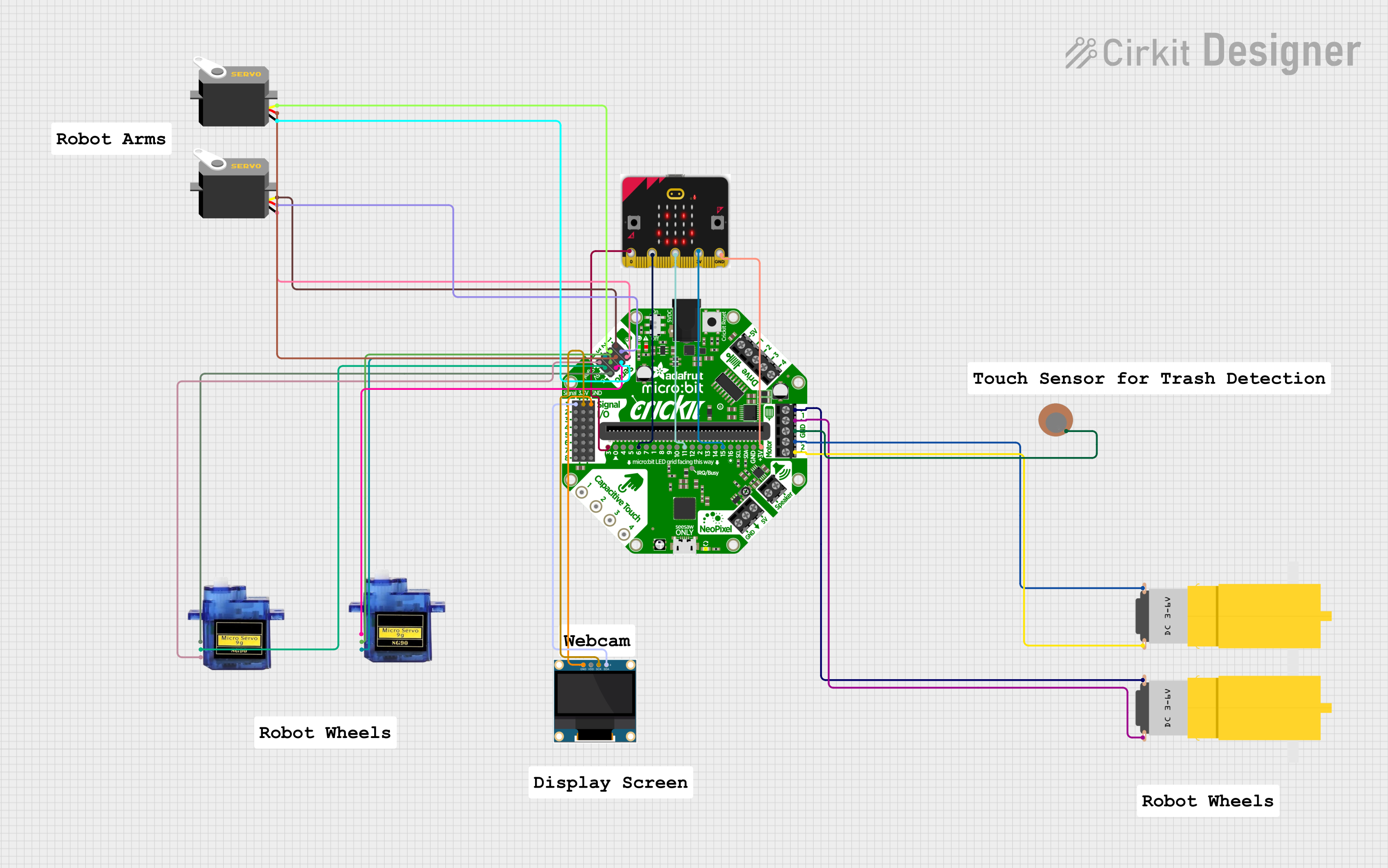


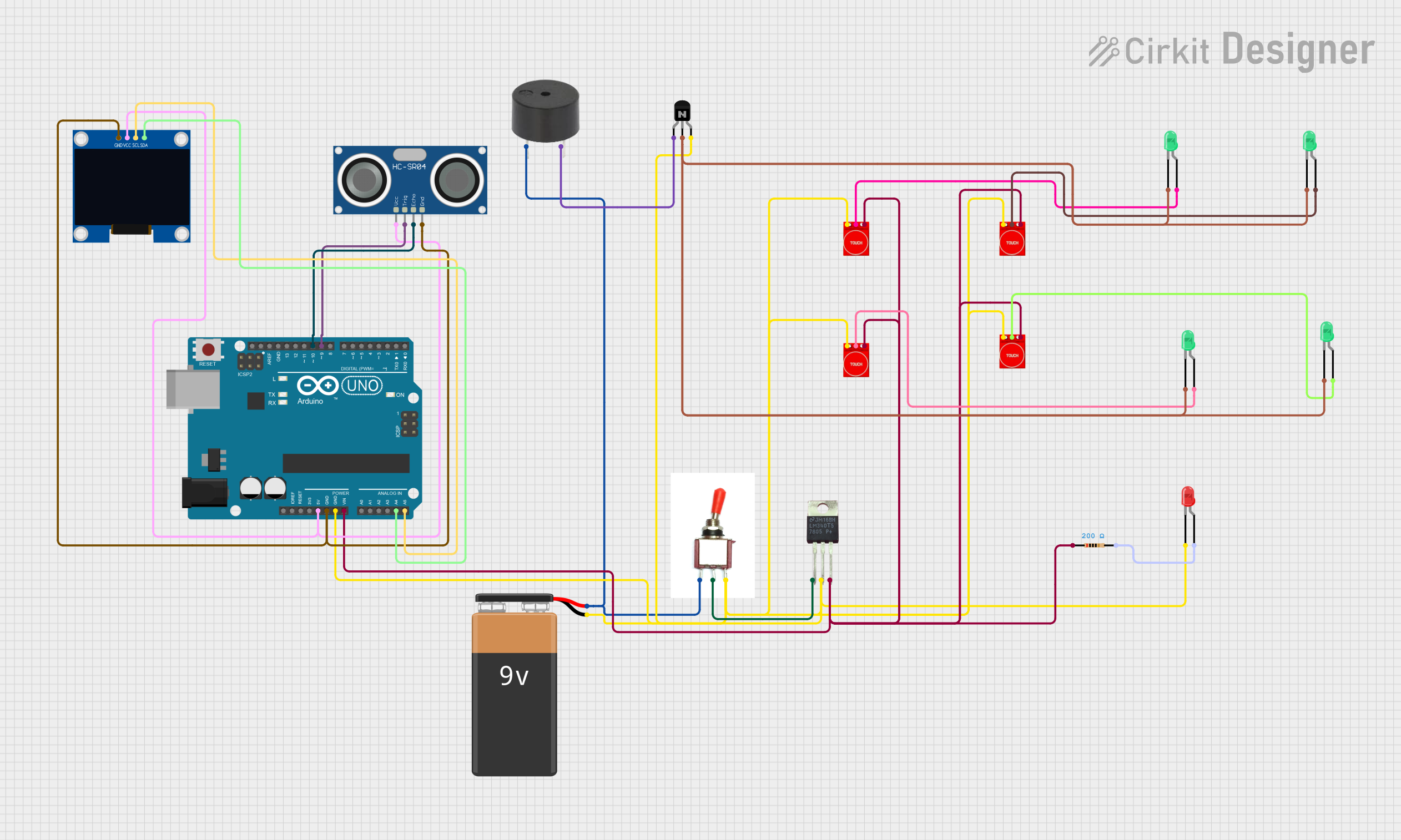
Explore Projects Built with Micro:bit
Common Applications and Use Cases
- Educational tools for teaching programming and electronics
- Interactive projects such as games, wearable devices, and robotics
- Prototyping IoT (Internet of Things) applications
- Data collection and analysis using built-in sensors
- Wireless communication and control using Bluetooth
Technical Specifications
The Micro:bit is equipped with a variety of features that make it versatile and easy to use. Below are its key technical details:
Key Features
- Microcontroller: Nordic nRF52833 (ARM Cortex-M4, 64 MHz)
- Memory: 512 KB Flash, 128 KB RAM
- Power Supply: 3V to 3.3V (via USB or battery pack)
- Connectivity: Bluetooth Low Energy (BLE), USB, I2C, SPI, GPIO
- Sensors: Accelerometer, magnetometer, temperature sensor, light sensor
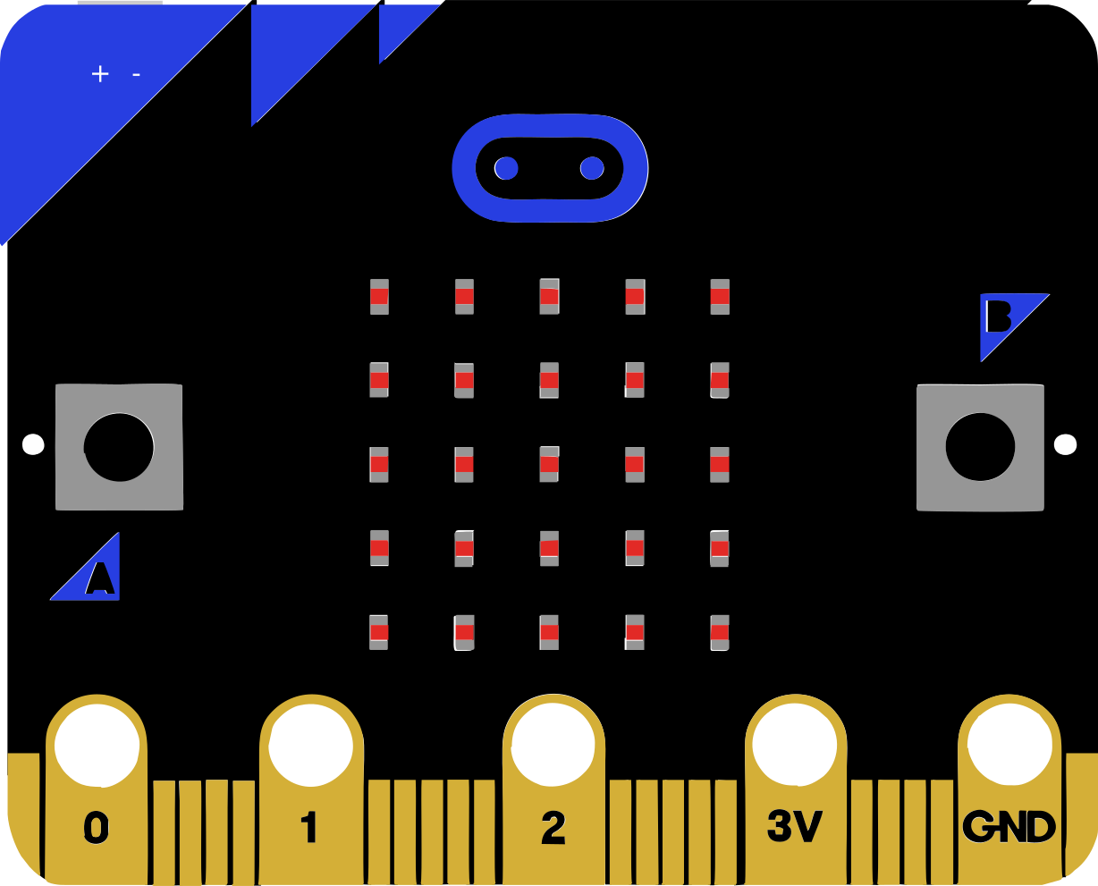
- Display: 5x5 LED matrix
- Buttons: 2 programmable buttons (A and B)
- I/O Pins: 25 edge connector pins (3 are large and crocodile-clip friendly)
Pin Configuration and Descriptions
The Micro:bit has a 25-pin edge connector, with specific pins designed for power, input/output, and communication. Below is a table summarizing the key pins:
| Pin Number | Name | Description |
|---|---|---|
| 0 | P0 | General-purpose I/O pin, often used for analog input or digital output |
| 1 | P1 | General-purpose I/O pin, often used for analog input or digital output |
| 2 | P2 | General-purpose I/O pin, often used for analog input or digital output |
| 3V | 3V Power | Provides 3V power output for external components |
| GND | Ground | Ground connection for the circuit |
| 19, 20 | I2C (SCL, SDA) | I2C communication pins for connecting sensors and peripherals |
| 21, 22 | SPI (MOSI, MISO, SCK) | SPI communication pins for high-speed data transfer |
| 25 | LED Matrix | Controls the 5x5 LED matrix display |
| 26, 27 | Button A, B | Input pins for the two onboard buttons |
Usage Instructions
The Micro:bit is designed to be beginner-friendly and can be programmed using block-based editors, Python, or JavaScript. Below are the steps to use the Micro:bit in a circuit and some best practices.
Getting Started
- Power the Micro:bit: Connect the Micro:bit to your computer using a micro-USB cable or use a battery pack for portable projects.
- Choose a Programming Environment:
- Use the Microsoft MakeCode editor for block-based programming.
- Use Python with the MicroPython editor for more advanced projects.
- Write and Upload Code:
- Write your code in the chosen editor.
- Download the
.hexfile and drag it to the Micro:bit drive that appears on your computer.
- Connect External Components:
- Use crocodile clips or jumper wires to connect external components to the edge connector pins.
- Ensure proper polarity and voltage levels to avoid damaging the Micro:bit.
Example: Blinking LED with Micro:bit
Here is an example of how to blink an external LED connected to pin P0 using MicroPython:
from microbit import *
Connect the positive leg of the LED to pin P0 and the negative leg to GND
while True: pin0.write_digital(1) # Turn the LED on sleep(1000) # Wait for 1 second pin0.write_digital(0) # Turn the LED off sleep(1000) # Wait for 1 second
Important Considerations and Best Practices
- Voltage Levels: Ensure external components operate at 3.3V to avoid damaging the Micro:bit.
- Pin Limitations: Avoid drawing more than 90mA total from the Micro:bit's pins.
- Static Protection: Handle the Micro:bit by its edges to prevent static damage.
- Firmware Updates: Keep the Micro:bit firmware updated for compatibility with the latest tools.
Troubleshooting and FAQs
Common Issues and Solutions
Micro:bit Not Recognized by Computer:
- Ensure the USB cable is a data cable (not just a charging cable).
- Try a different USB port or cable.
- Check if the Micro:bit's power LED is on.
Code Not Running:
- Verify that the
.hexfile was successfully copied to the Micro:bit. - Check for syntax errors in your code.
- Reset the Micro:bit by pressing the reset button on the back.
- Verify that the
External Components Not Working:
- Double-check connections to the edge connector pins.
- Ensure the components are compatible with 3.3V logic levels.
- Test the components separately to confirm they are functional.
FAQs
Can I use the Micro:bit with Arduino components? Yes, many Arduino-compatible components (e.g., sensors, LEDs) can be used with the Micro:bit, provided they operate at 3.3V.
How do I reset the Micro:bit? Press the small reset button on the back of the board. This will restart the program.
Can I use Bluetooth and USB simultaneously? No, Bluetooth functionality is disabled when the Micro:bit is connected to a computer via USB.
By following this documentation, you can effectively use the Micro:bit to create a wide range of interactive and educational projects!