How to Use DFRobot Solar Power Manager 5V: Examples, Pinouts, and Specs
Introduction
The DFRobot Solar Power Manager 5V is a compact and efficient solar power management module designed to regulate and manage solar energy. It provides a stable 5V output, making it ideal for powering low-power devices and charging lithium-ion or lithium-polymer batteries. This module is specifically engineered to maximize the efficiency of solar energy harvesting while ensuring safe and reliable operation.
Explore Projects Built with DFRobot Solar Power Manager 5V
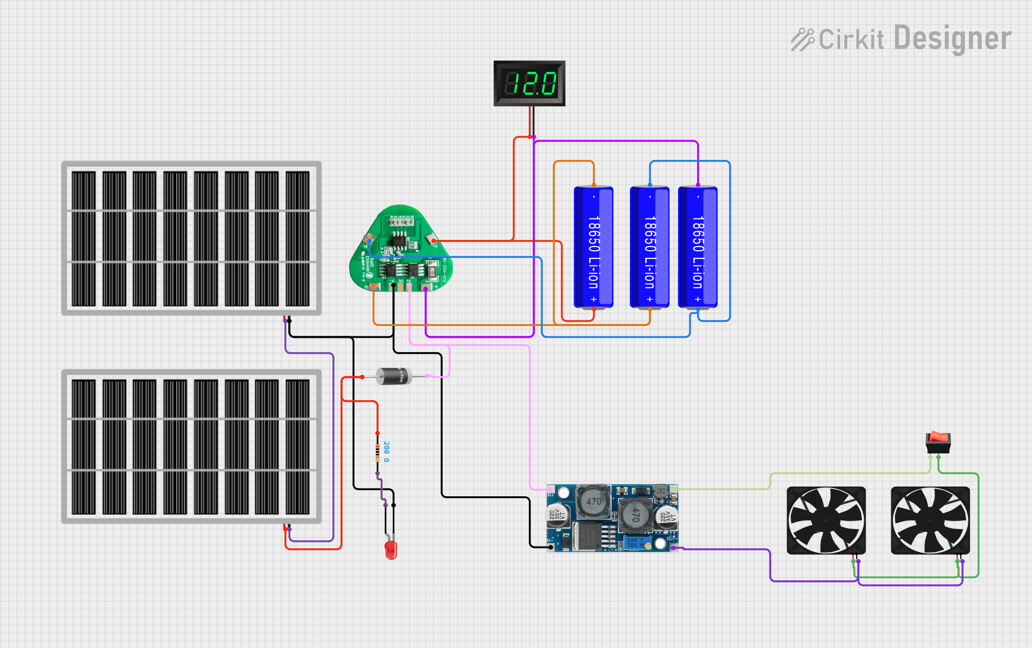
Explore Projects Built with DFRobot Solar Power Manager 5V
Common Applications and Use Cases
- Solar-powered IoT devices
- Outdoor environmental monitoring systems
- Remote sensing and data logging
- Portable solar charging stations
- DIY solar energy projects
Technical Specifications
The following table outlines the key technical specifications of the DFRobot Solar Power Manager 5V:
| Parameter | Value |
|---|---|
| Input Voltage Range | 4.4V to 6V (solar panel or USB input) |
| Output Voltage | 5V (regulated) |
| Output Current (Max) | 1A |
| Battery Charging Voltage | 4.2V (for single-cell Li-ion/LiPo batteries) |
| Battery Charging Current | 500mA (default, adjustable) |
| Efficiency | Up to 96% |
| Operating Temperature | -40°C to 85°C |
| Dimensions | 54mm x 32mm |
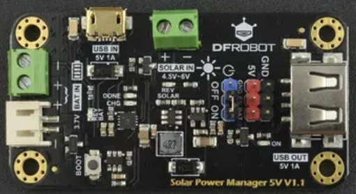
Pin Configuration and Descriptions
The DFRobot Solar Power Manager 5V features several input/output pins and connectors. The table below describes each pin:
| Pin/Connector | Type | Description |
|---|---|---|
| Solar Input | JST Connector | Connects to a solar panel (4.4V to 6V input range). |
| USB Input | Micro-USB | Alternative power input for USB charging (5V). |
| Battery Connector | JST Connector | Connects to a single-cell Li-ion/LiPo battery. |
| 5V Output | JST Connector | Provides a regulated 5V output for powering external devices. |
| CHG Indicator LED | LED | Lights up during battery charging. |
| PWR Indicator LED | LED | Lights up when the module is powered. |
| MPPT Adjustment | Potentiometer | Adjusts the Maximum Power Point Tracking (MPPT) for optimal solar efficiency. |
Usage Instructions
How to Use the Component in a Circuit
- Connect the Solar Panel: Attach a solar panel (4.4V to 6V) to the
Solar Inputconnector. Ensure the panel's polarity matches the connector. - Connect the Battery: Plug a single-cell Li-ion or LiPo battery into the
Battery Connector. The module will automatically manage charging. - Power External Devices: Use the
5V Outputconnector to power your device. Ensure the connected device does not exceed the 1A output current limit. - Optional USB Input: If solar power is unavailable, connect a 5V USB power source to the
USB Inputport to charge the battery or power devices.
Important Considerations and Best Practices
- Battery Selection: Use only single-cell Li-ion or LiPo batteries with a nominal voltage of 3.7V and a maximum charging voltage of 4.2V.
- MPPT Adjustment: Use the onboard potentiometer to fine-tune the MPPT for your specific solar panel. This ensures maximum energy harvesting efficiency.
- Heat Dissipation: Avoid placing the module in direct sunlight or enclosed spaces without ventilation, as it may overheat during operation.
- Load Current: Ensure the total current drawn by connected devices does not exceed 1A to prevent damage to the module.
Example: Using with an Arduino UNO
The DFRobot Solar Power Manager 5V can be used to power an Arduino UNO. Below is an example setup:
- Connect the
5V Outputof the module to the5Vpin of the Arduino UNO. - Connect the
GNDpin of the module to theGNDpin of the Arduino UNO. - Ensure the solar panel and battery are properly connected to the module.
Here is a simple Arduino sketch to blink an LED while powered by the Solar Power Manager:
// Simple LED Blink Example
// This code blinks an LED connected to pin 13 of the Arduino UNO.
// Ensure the Arduino is powered via the DFRobot Solar Power Manager 5V.

void setup() {
  pinMode(13, OUTPUT); // Set pin 13 as an output pin
}

void loop() {
  digitalWrite(13, HIGH); // Turn the LED on
  delay(1000);            // Wait for 1 second
  digitalWrite(13, LOW);  // Turn the LED off
  delay(1000);            // Wait for 1 second
}
Troubleshooting and FAQs
Common Issues and Solutions
The module does not power the connected device:
- Ensure the solar panel or USB input is providing sufficient voltage (4.4V to 6V).
- Check the battery connection and ensure the battery is not over-discharged.
- Verify that the connected device does not exceed the 1A output current limit.
The battery is not charging:
- Confirm that the solar panel is receiving adequate sunlight.
- Check the polarity of the battery connection.
- Adjust the MPPT potentiometer to match the solar panel's characteristics.
The module overheats:
- Ensure proper ventilation and avoid placing the module in direct sunlight.
- Reduce the load current if it exceeds the module's capacity.
FAQs
Q: Can I use a higher voltage solar panel with this module?
A: No, the input voltage range is limited to 4.4V to 6V. Using a higher voltage panel may damage the module.
Q: Can I use this module without a battery?
A: Yes, the module can operate without a battery, but it is recommended to use a battery for stable operation and energy storage.
Q: How do I adjust the MPPT for my solar panel?
A: Use the onboard potentiometer to fine-tune the MPPT. Rotate the potentiometer while monitoring the output voltage and current to achieve maximum efficiency.
Q: Is the module waterproof?
A: No, the module is not waterproof. It should be used in a dry environment or enclosed in a waterproof case for outdoor applications.