How to Use Control Relay: Examples, Pinouts, and Specs
Introduction
The Siemens 3RH2262-1BB40 Control Relay is an electromechanical switch designed to control circuits using a low-power signal. It is widely used in industrial automation, motor control, and other applications where multiple circuits need to be controlled with a single input signal. The relay consists of a coil, an armature, and contacts that open or close when the coil is energized, enabling efficient and reliable switching.
Explore Projects Built with Control Relay


Explore Projects Built with Control Relay
Common Applications and Use Cases
- Industrial automation systems
- Motor control circuits
- Signal amplification and isolation
- Switching multiple circuits with a single control signal
- Safety interlocks in machinery
Technical Specifications
Below are the key technical details of the Siemens 3RH2262-1BB40 Control Relay:
General Specifications
| Parameter | Value |
|---|---|
| Manufacturer | Siemens |
| Part Number | 3RH2262-1BB40 |
| Type | Control Relay |
| Coil Voltage | 24 V DC |
| Contact Configuration | 2 NO (Normally Open) + 2 NC (Normally Closed) |
| Rated Current (Contacts) | 10 A |
| Operating Temperature | -25°C to +60°C |
| Mounting Type | DIN Rail |
| Dimensions (L x W x H) | 45 mm x 75 mm x 90 mm |
| Weight | 0.2 kg |
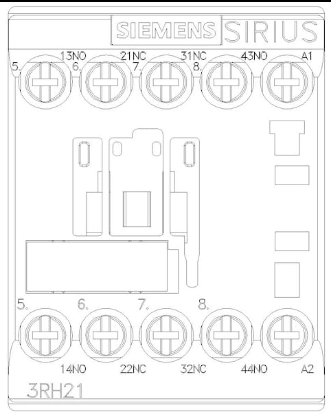
Pin Configuration and Descriptions
The relay has a total of 8 pins, which are configured as follows:
| Pin Number | Description |
|---|---|
| 1 | Coil Positive Terminal (+) |
| 2 | Coil Negative Terminal (-) |
| 3 | Normally Open (NO) Contact 1 Input |
| 4 | Normally Open (NO) Contact 1 Output |
| 5 | Normally Closed (NC) Contact 1 Input |
| 6 | Normally Closed (NC) Contact 1 Output |
| 7 | Normally Open (NO) Contact 2 Input |
| 8 | Normally Open (NO) Contact 2 Output |
Usage Instructions
How to Use the Control Relay in a Circuit
- Power the Coil: Connect the coil terminals (pins 1 and 2) to a 24 V DC power source. Ensure the polarity is correct.
- Connect the Load:
- For normally open (NO) contacts, connect the input to pin 3 or 7 and the output to pin 4 or 8.
- For normally closed (NC) contacts, connect the input to pin 5 and the output to pin 6.
- Switching Operation: When the coil is energized, the NO contacts close, and the NC contacts open, allowing the relay to control the connected circuits.
Important Considerations and Best Practices
- Voltage and Current Ratings: Ensure the connected load does not exceed the rated current of 10 A and the rated voltage of the relay.
- Back-EMF Protection: Use a flyback diode across the coil terminals to protect the circuit from voltage spikes when the coil is de-energized.
- Proper Mounting: Mount the relay securely on a DIN rail to prevent vibration or movement during operation.
- Isolation: Use the relay to isolate high-power circuits from low-power control signals for safety and reliability.
Example: Connecting the Relay to an Arduino UNO
The Siemens 3RH2262-1BB40 can be controlled using an Arduino UNO. Below is an example circuit and code:
Circuit Connections
- Connect the relay coil positive terminal (pin 1) to a digital output pin on the Arduino (e.g., pin 7) through a transistor.
- Connect the relay coil negative terminal (pin 2) to the Arduino GND.
- Use a flyback diode across the coil terminals to protect the Arduino.
- Connect the load to the NO or NC contacts as required.
Arduino Code
// Define the relay control pin
const int relayPin = 7;

void setup() {
  // Set the relay pin as an output
  pinMode(relayPin, OUTPUT);
  // Initialize the relay in the OFF state
  digitalWrite(relayPin, LOW);
}

void loop() {
  // Turn the relay ON
  digitalWrite(relayPin, HIGH);
  delay(5000); // Keep the relay ON for 5 seconds

  // Turn the relay OFF
  digitalWrite(relayPin, LOW);
  delay(5000); // Keep the relay OFF for 5 seconds
}
Troubleshooting and FAQs
Common Issues and Solutions
Relay Not Switching:
- Cause: Insufficient voltage or current to the coil.
- Solution: Verify the power supply to the coil is 24 V DC and capable of providing sufficient current.
Contacts Not Closing or Opening:
- Cause: Mechanical failure or excessive load.
- Solution: Check the load does not exceed the rated current of 10 A. Inspect the relay for physical damage.
Arduino Not Controlling the Relay:
- Cause: Incorrect wiring or missing flyback diode.
- Solution: Double-check the wiring and ensure a flyback diode is installed across the coil terminals.
Excessive Heat:
- Cause: Overloading or poor ventilation.
- Solution: Reduce the load or improve ventilation around the relay.
FAQs
Q1: Can I use this relay with an AC coil voltage?
A1: No, the Siemens 3RH2262-1BB40 is designed for a 24 V DC coil voltage only.
Q2: What is the maximum switching frequency of this relay?
A2: The maximum switching frequency is approximately 10 Hz under normal operating conditions.
Q3: Can I use this relay to switch high-power motors?
A3: Yes, but ensure the motor's starting current does not exceed the relay's rated current of 10 A. Use a contactor for higher currents.
Q4: Is the relay suitable for outdoor use?
A4: No, the relay is not weatherproof and should be used in a dry, indoor environment.