
How to Use HMI Kinco MT508T: Examples, Pinouts, and Specs
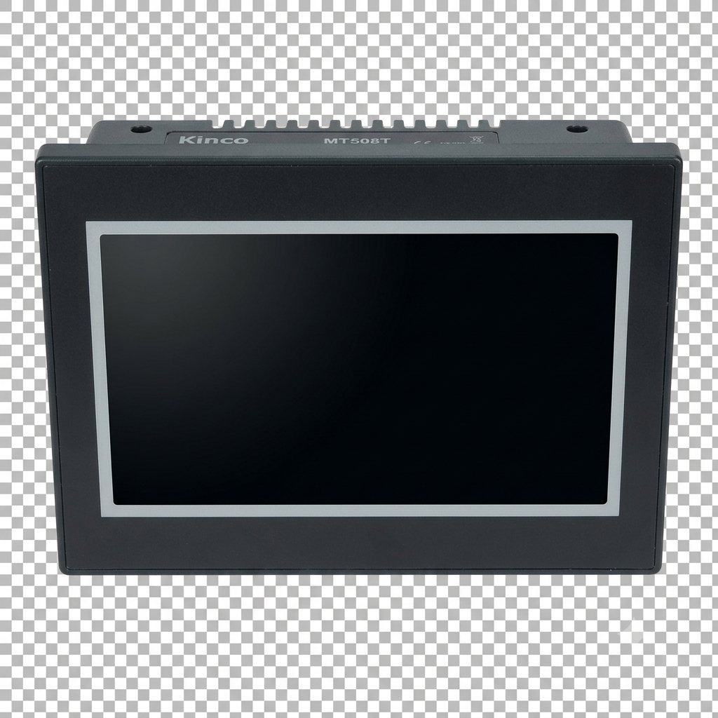
 Design with HMI Kinco MT508T in Cirkit Designer
Introduction
The HMI Kinco MT508T is a human-machine interface (HMI) designed for industrial automation applications. It features a 5.7-inch touchscreen display, enabling operators to monitor and control machinery and processes through intuitive graphical user interfaces (GUIs). This device supports multiple communication protocols, making it highly versatile for integration with a wide range of programmable logic controllers (PLCs) and other industrial devices.
Explore Projects Built with HMI Kinco MT508T
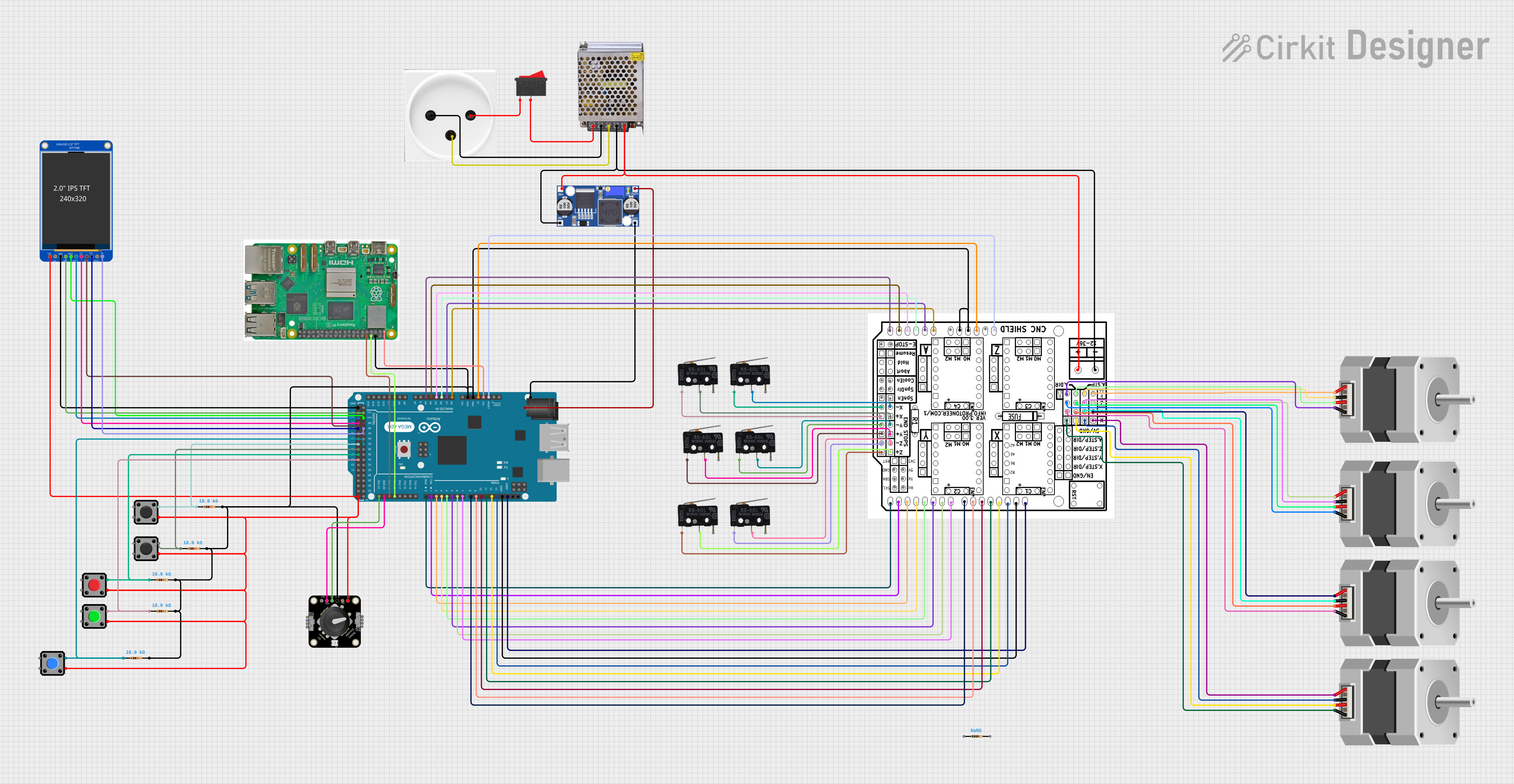 Open Project in Cirkit Designer
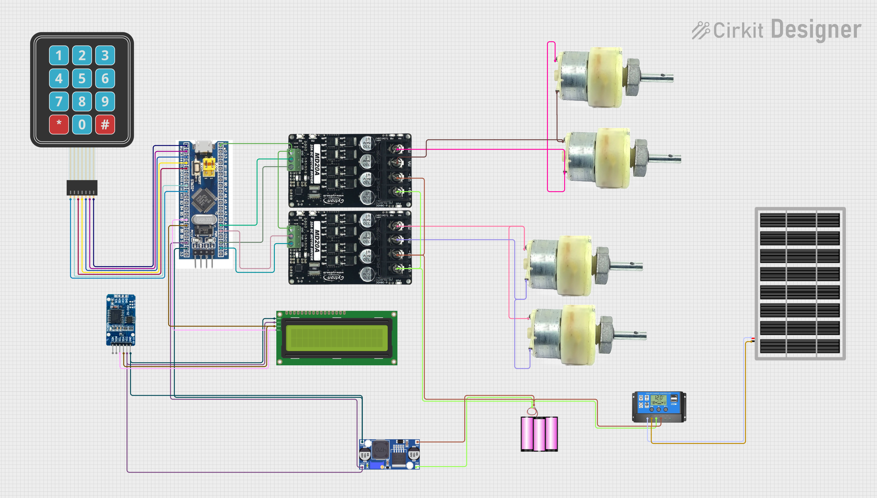 Open Project in Cirkit Designer
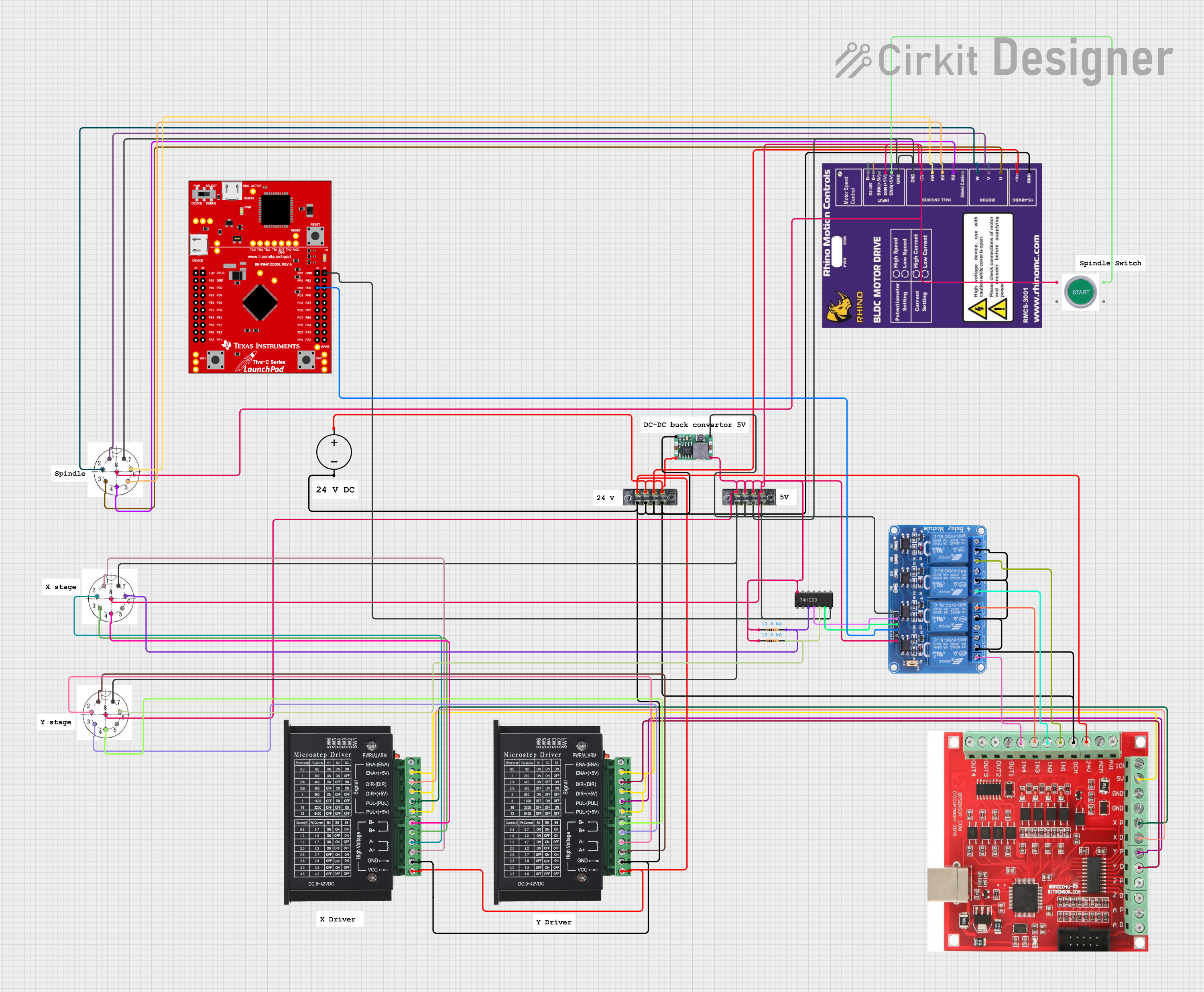 Open Project in Cirkit Designer
 Open Project in Cirkit Designer
Explore Projects Built with HMI Kinco MT508T
Open Project in Cirkit DesignerOpen Project in Cirkit DesignerOpen Project in Cirkit DesignerOpen Project in Cirkit DesignerCommon Applications and Use Cases
- Industrial process monitoring and control
- Factory automation systems
- Machine operation interfaces
- Data visualization for PLCs and sensors
- Integration with SCADA systems
Technical Specifications
Key Technical Details
| Specification | Value |
|---|---|
| Display Size | 5.7 inches |
| Display Type | TFT LCD with 256 colors |
| Resolution | 320 x 240 pixels (QVGA) |
| Touchscreen Type | Resistive |
| Processor | 32-bit RISC CPU |
| Memory | 4 MB Flash, 64 KB RAM |
| Communication Ports | RS232, RS485, and USB |
| Input Voltage | 24 V DC (±10%) |
| Power Consumption | < 5 W |
| Operating Temperature Range | 0°C to 50°C |
| Storage Temperature Range | -20°C to 60°C |
| Dimensions | 195 mm x 145 mm x 44 mm |
| Weight | Approximately 0.8 kg |
Pin Configuration and Descriptions
The HMI Kinco MT508T features multiple communication ports for connecting to external devices. Below is a description of the key ports and their pin configurations:
RS232 Port Pinout
| Pin Number | Signal Name | Description |
|---|---|---|
| 1 | DCD | Data Carrier Detect |
| 2 | RXD | Receive Data |
| 3 | TXD | Transmit Data |
| 4 | DTR | Data Terminal Ready |
| 5 | GND | Ground |
| 6 | DSR | Data Set Ready |
| 7 | RTS | Request to Send |
| 8 | CTS | Clear to Send |
| 9 | RI | Ring Indicator |
RS485 Port Pinout
| Pin Number | Signal Name | Description |
|---|---|---|
| 1 | A (+) | Positive Data Line |
| 2 | B (-) | Negative Data Line |
| 3 | GND | Ground |
Power Input Terminal
| Pin Number | Signal Name | Description |
|---|---|---|
| 1 | +24V | Positive DC Voltage Input |
| 2 | GND | Ground |
Usage Instructions
How to Use the HMI Kinco MT508T in a Circuit
- Power Connection: Connect the +24V DC power supply to the power input terminal. Ensure the power supply is stable and within the specified voltage range (24V ±10%).
- Communication Setup:
- Use the RS232 or RS485 port to connect the HMI to a PLC or other controller.
- Configure the communication parameters (baud rate, parity, stop bits, etc.) in the HMI software to match the connected device.
- Software Configuration:
- Use Kinco's HMIware software to design and upload graphical user interfaces (GUIs) to the device.
- Create buttons, indicators, and other elements to interact with the connected machinery.
- Testing:
- Power on the HMI and verify that it communicates correctly with the connected device.
- Test the GUI functionality to ensure proper operation.
Important Considerations and Best Practices
- Power Supply: Use a regulated power supply to avoid voltage fluctuations that could damage the device.
- Grounding: Ensure proper grounding to prevent electrical noise from interfering with communication.
- Communication Protocols: Verify that the HMI and the connected device use compatible communication protocols.
- Environmental Conditions: Operate the device within the specified temperature range (0°C to 50°C) to ensure reliability.
- Firmware Updates: Regularly check for firmware updates from Kinco to improve performance and add new features.
Example: Connecting to an Arduino UNO
The HMI Kinco MT508T can be connected to an Arduino UNO via the RS232 port using a TTL-to-RS232 converter. Below is an example Arduino sketch for basic communication:
#include <SoftwareSerial.h>

// Define RX and TX pins for SoftwareSerial
SoftwareSerial mySerial(10, 11); // RX = pin 10, TX = pin 11

void setup() {
  // Initialize serial communication with the HMI
  mySerial.begin(9600); // Set baud rate to match HMI configuration
  Serial.begin(9600);   // For debugging via Serial Monitor

  // Send an initial message to the HMI
  mySerial.println("Hello, HMI!");
  Serial.println("Message sent to HMI.");
}

void loop() {
  // Check if data is available from the HMI
  if (mySerial.available()) {
    String dataFromHMI = mySerial.readString(); // Read data from HMI
    Serial.println("Received from HMI: " + dataFromHMI);
  }

  // Send data to the HMI periodically
  mySerial.println("Arduino says hello!");
  delay(1000); // Wait 1 second before sending the next message
}
Note: Ensure the HMI's communication settings (baud rate, data bits, etc.) match the Arduino's configuration.
Troubleshooting and FAQs
Common Issues and Solutions
HMI Not Powering On:
- Cause: Incorrect or unstable power supply.
- Solution: Verify the power supply voltage is 24V DC (±10%) and properly connected.
No Communication with PLC/Arduino:
- Cause: Mismatched communication settings.
- Solution: Check and match the baud rate, parity, and stop bits between the HMI and the connected device.
Touchscreen Not Responding:
- Cause: Calibration issue or hardware fault.
- Solution: Recalibrate the touchscreen using the HMI settings menu. If the issue persists, contact Kinco support.
Display Issues (e.g., Blank Screen):
- Cause: Faulty firmware or hardware.
- Solution: Re-upload the GUI project using HMIware software. If the problem continues, inspect the hardware for damage.
FAQs
Q1: Can the HMI Kinco MT508T connect to multiple devices simultaneously?
A1: Yes, the HMI supports multiple communication ports (RS232, RS485, and USB), allowing it to connect to multiple devices. However, ensure proper configuration to avoid conflicts.
Q2: What software is required to program the HMI?
A2: The HMI Kinco MT508T is programmed using Kinco's HMIware software, which is available for download from the Kinco website.
Q3: Is the HMI compatible with Modbus protocol?
A3: Yes, the HMI supports Modbus RTU protocol, making it compatible with many industrial devices.
Q4: How do I update the firmware?
A4: Firmware updates can be performed via the USB port using the update tool provided by Kinco. Follow the instructions in the firmware update guide.
Q5: Can the HMI be used outdoors?
A5: The HMI is not designed for outdoor use. It should be operated in a controlled indoor environment within the specified temperature range.