How to Use rlyr998: Examples, Pinouts, and Specs
Introduction
The RLYR998, manufactured by Reyax, is a relay component designed for use in electronic circuits to control high-power loads using low-power signals. It functions as an electrically operated switch, allowing users to open or close a circuit when a control signal is applied. This relay provides electrical isolation between the control circuit and the load circuit, ensuring safety and reliability in various applications.
Explore Projects Built with rlyr998
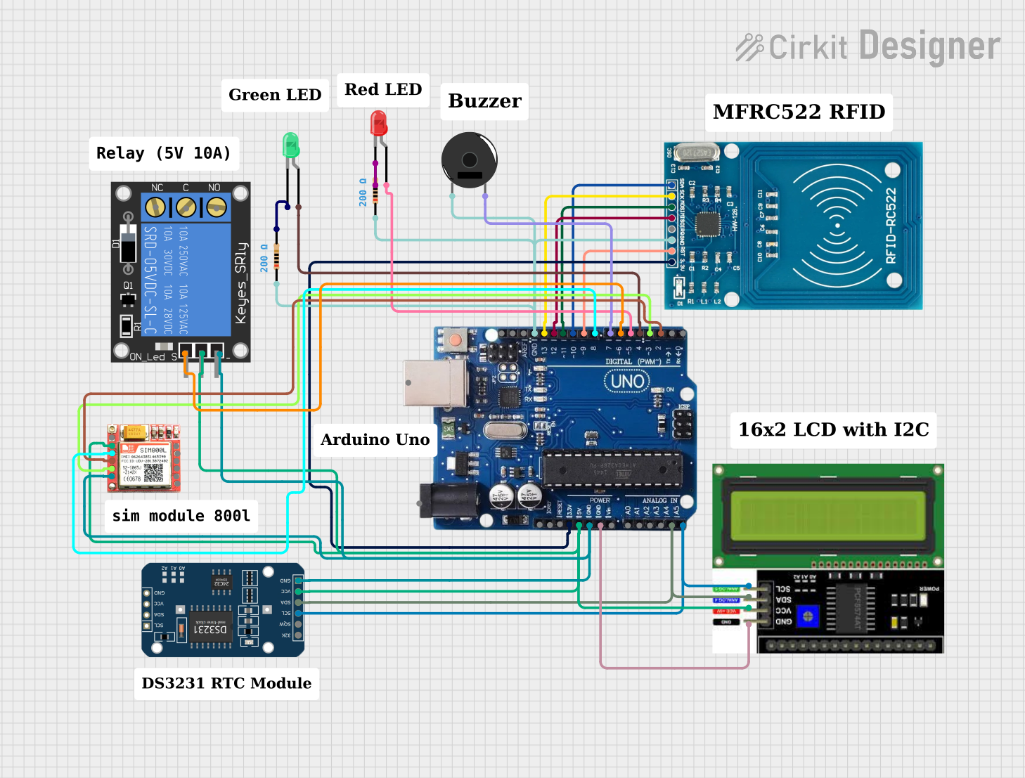

![Image of [Circuit Design] RFID-Based Equipment Logger for DPWH : A project utilizing rlyr998 in a practical application](https://abacasstorageaccnt.blob.core.windows.net/cirkit/c81f4194-7010-43d8-91fe-f2eb970df771.png)
Explore Projects Built with rlyr998
Common Applications and Use Cases
- Home automation systems (e.g., controlling lights, fans, or appliances)
- Industrial control systems
- Motor control circuits
- Power distribution and switching
- Signal isolation in sensitive electronic systems
Technical Specifications
The RLYR998 relay is designed to handle a wide range of applications with the following key specifications:
| Parameter | Value |
|---|---|
| Operating Voltage | 5V DC |
| Coil Resistance | 70 Ω |
| Switching Voltage (Max) | 250V AC / 30V DC |
| Switching Current (Max) | 10A |
| Contact Configuration | SPDT (Single Pole Double Throw) |
| Contact Material | Silver Alloy |
| Insulation Resistance | ≥ 100 MΩ (at 500V DC) |
| Dielectric Strength | 1500V AC (between coil and contacts) |
| Operating Temperature | -40°C to +85°C |
| Dimensions | 19mm x 15mm x 15mm |
| Weight | 10g |
Pin Configuration and Descriptions
The RLYR998 relay has a standard 5-pin configuration. The table below describes each pin:
| Pin Number | Name | Description |
|---|---|---|
| 1 | Coil+ | Positive terminal of the relay coil (connect to control signal or power source). |
| 2 | Coil- | Negative terminal of the relay coil (connect to ground). |
| 3 | Common (COM) | Common terminal for the load circuit. |
| 4 | Normally Open (NO) | Open circuit when the relay is inactive; closes when the relay is activated. |
| 5 | Normally Closed (NC) | Closed circuit when the relay is inactive; opens when the relay is activated. |
Usage Instructions
How to Use the RLYR998 in a Circuit
- Power the Relay Coil: Connect the
Coil+pin to a control signal or power source (e.g., 5V DC) and theCoil-pin to ground. Ensure the control signal matches the relay's operating voltage. - Connect the Load Circuit:
- Connect the load's power source to the
COMpin. - Use the
NOpin if you want the load to be powered only when the relay is activated. - Use the
NCpin if you want the load to be powered when the relay is inactive.
- Connect the load's power source to the
- Control the Relay: Apply a control signal to the relay coil to activate or deactivate the relay, switching the load circuit on or off.
Important Considerations and Best Practices
- Flyback Diode: Always connect a flyback diode across the relay coil to protect the control circuit from voltage spikes caused by the collapsing magnetic field when the relay is deactivated.
- Current Ratings: Ensure the load's current does not exceed the relay's maximum switching current (10A).
- Isolation: Use the relay to isolate high-power circuits from low-power control circuits for safety.
- Mounting: Secure the relay properly to prevent vibrations or movement that could affect performance.
Example: Connecting the RLYR998 to an Arduino UNO
Below is an example of how to control the RLYR998 relay using an Arduino UNO:
// Define the pin connected to the relay's Coil+ terminal
const int relayPin = 7;

void setup() {
  // Set the relay pin as an output
  pinMode(relayPin, OUTPUT);
}

void loop() {
  // Activate the relay (turn on the load)
  digitalWrite(relayPin, HIGH);
  delay(5000); // Keep the relay on for 5 seconds

  // Deactivate the relay (turn off the load)
  digitalWrite(relayPin, LOW);
  delay(5000); // Keep the relay off for 5 seconds
}
Note: Ensure the relay's Coil+ pin is connected to the Arduino's digital pin (e.g., pin 7), and the Coil- pin is connected to the Arduino's ground (GND). Use a transistor or relay driver circuit if the relay requires more current than the Arduino pin can supply.
Troubleshooting and FAQs
Common Issues and Solutions
Relay Not Activating:
- Cause: Insufficient control voltage or current.
- Solution: Verify that the control signal matches the relay's operating voltage (5V DC). Use a transistor or relay driver circuit if necessary.
Load Not Switching:
- Cause: Incorrect wiring of the load circuit.
- Solution: Double-check the connections to the
COM,NO, andNCpins. Ensure the load is properly connected and powered.
Voltage Spikes Damaging the Circuit:
- Cause: Lack of a flyback diode across the relay coil.
- Solution: Install a flyback diode (e.g., 1N4007) across the
Coil+andCoil-pins, with the cathode connected toCoil+.
Relay Overheating:
- Cause: Exceeding the relay's maximum current rating.
- Solution: Ensure the load's current does not exceed 10A. Use a higher-rated relay if necessary.
FAQs
Q: Can the RLYR998 be used with AC loads?
A: Yes, the RLYR998 can switch AC loads up to 250V, provided the current does not exceed 10A.
Q: Is the relay suitable for PWM control?
A: No, relays like the RLYR998 are not designed for high-speed switching. Use a solid-state relay or transistor for PWM applications.
Q: How do I know if the relay is activated?
A: You can use an LED in the control circuit to indicate when the relay is activated, or check the state of the load circuit (e.g., whether the load is powered).
Q: Can I use the RLYR998 with a 3.3V control signal?
A: No, the RLYR998 requires a 5V control signal. Use a level shifter or transistor to interface with 3.3V systems.