
How to Use CD4047: Examples, Pinouts, and Specs
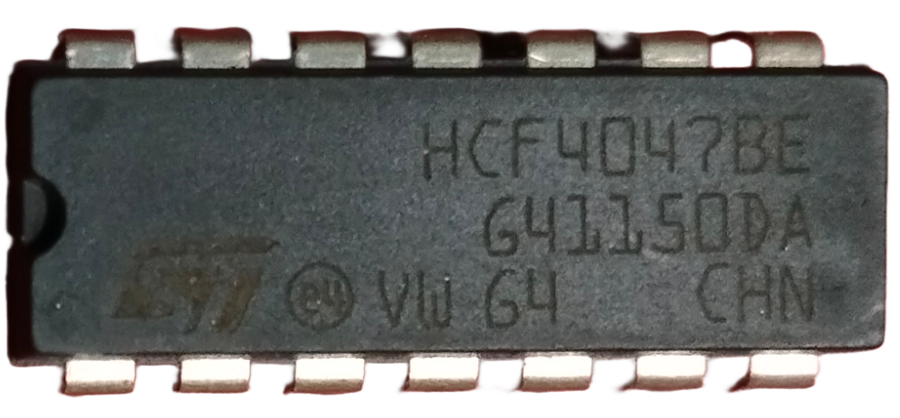
 Design with CD4047 in Cirkit Designer
Introduction
The CD4047 is a versatile monostable and astable multivibrator IC manufactured by Texas Instruments. It is designed to generate precise timing pulses and oscillations, making it a popular choice for applications requiring stable frequency generation, waveform shaping, and timer circuits. The IC is highly reliable and easy to use, making it suitable for both beginners and advanced users in electronics.
Explore Projects Built with CD4047
 Open Project in Cirkit Designer
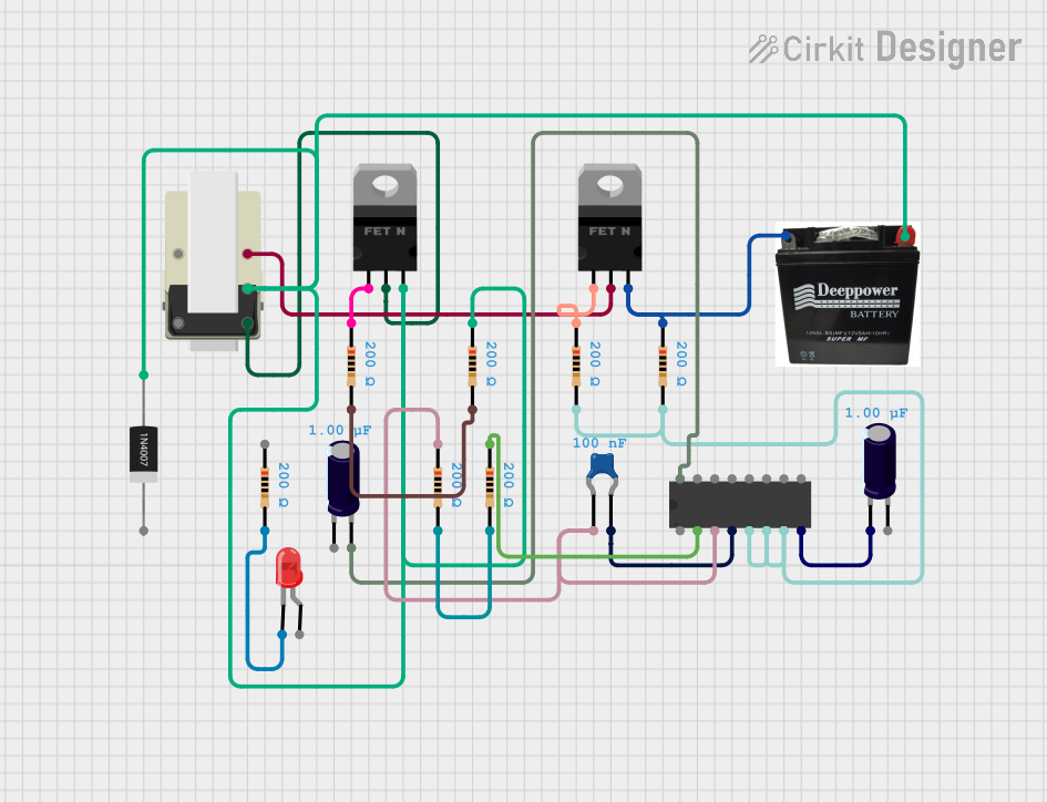 Open Project in Cirkit Designer
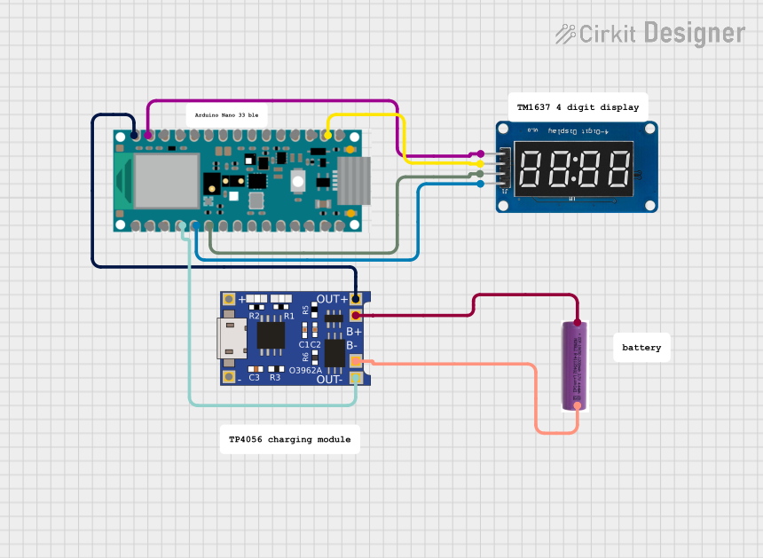 Open Project in Cirkit Designer
 Open Project in Cirkit Designer
Explore Projects Built with CD4047
Open Project in Cirkit DesignerOpen Project in Cirkit DesignerOpen Project in Cirkit DesignerOpen Project in Cirkit DesignerCommon Applications
- Frequency generation for oscillators
- Pulse generation for timing circuits
- Waveform shaping in signal processing
- LED and lamp flashers
- Clock pulse generation for digital circuits
- Frequency division and signal gating
Technical Specifications
The CD4047 IC is a CMOS-based device with low power consumption and high noise immunity. Below are its key technical details:
Key Technical Details
- Operating Voltage Range: 3V to 15V
- Typical Supply Voltage: 5V, 9V, or 12V
- Maximum Supply Voltage: 18V
- Output Current: 10mA (maximum per output pin)
- Operating Temperature Range: -55°C to +125°C
- Power Dissipation: 500mW (maximum)
- Frequency Range (Astable Mode): Up to 1MHz
- Propagation Delay: 200ns (typical at 5V)
Pin Configuration and Descriptions
The CD4047 is a 14-pin IC with the following pinout:
| Pin No. | Pin Name | Description |
|---|---|---|
| 1 | ASTABLE | Input pin to enable astable mode |
| 2 | ASTABLE/RESET | Input pin to reset the IC in astable mode |
| 3 | C1 | External capacitor connection for timing configuration |
| 4 | R1 | External resistor connection for timing configuration |
| 5 | R2 | Optional external resistor for fine-tuning timing |
| 6 | GND | Ground (0V reference) |
| 7 | Q | Output pin for the primary waveform (non-inverted) |
| 8 | Q̅ (Q-bar) | Output pin for the complementary waveform (inverted) |
| 9 | VSS | Negative power supply (typically connected to GND) |
| 10 | VDD | Positive power supply (3V to 15V) |
| 11 | MONOSTABLE | Input pin to enable monostable mode |
| 12 | TRIGGER | Input pin to trigger the monostable operation |
| 13 | RESET | Input pin to reset the IC in monostable mode |
| 14 | NC | No connection (not used) |
Usage Instructions
Using the CD4047 in a Circuit
The CD4047 can operate in two modes: monostable and astable. Below are the steps to configure the IC for each mode:
1. Monostable Mode
- Connect a timing capacitor (C1) between Pin 3 and GND.
- Connect a timing resistor (R1) between Pin 4 and VDD.
- Apply a trigger pulse to Pin 12 (TRIGGER) to initiate the monostable operation.
- The output pulse width is determined by the formula: [ T = 2.48 \times R1 \times C1 ] where ( T ) is the pulse width in seconds, ( R1 ) is in ohms, and ( C1 ) is in farads.
- Use Pin 7 (Q) or Pin 8 (Q̅) for the output waveform.
2. Astable Mode
- Connect a timing capacitor (C1) between Pin 3 and GND.
- Connect a timing resistor (R1) between Pin 4 and VDD.
- Optionally, connect a second resistor (R2) between Pin 5 and GND for fine-tuning.
- Tie Pin 1 (ASTABLE) to VDD to enable astable mode.
- The output frequency is determined by the formula: [ f = \frac{1}{4.4 \times R1 \times C1} ] where ( f ) is the frequency in hertz, ( R1 ) is in ohms, and ( C1 ) is in farads.
- Use Pin 7 (Q) or Pin 8 (Q̅) for the output waveform.
Important Considerations
- Ensure the supply voltage (VDD) does not exceed 15V to avoid damaging the IC.
- Use decoupling capacitors (e.g., 0.1µF) across the power supply pins (VDD and GND) to reduce noise.
- For precise timing, use high-quality resistors and capacitors with low tolerance values.
- Avoid leaving unused input pins floating; connect them to GND or VDD as needed.
Example: Connecting CD4047 to Arduino UNO
The CD4047 can be used with an Arduino UNO to generate a square wave. Below is an example code to trigger the IC in monostable mode:
// Example: Triggering CD4047 in Monostable Mode with Arduino UNO
const int triggerPin = 7; // Arduino pin connected to CD4047 TRIGGER pin
const int outputPin = 8;  // Arduino pin connected to CD4047 Q output pin

void setup() {
  pinMode(triggerPin, OUTPUT); // Set trigger pin as output
  pinMode(outputPin, INPUT);   // Set output pin as input
  digitalWrite(triggerPin, LOW); // Initialize trigger pin to LOW
}

void loop() {
  // Generate a trigger pulse
  digitalWrite(triggerPin, HIGH); // Set trigger pin HIGH
  delay(10);                      // Wait for 10ms
  digitalWrite(triggerPin, LOW);  // Set trigger pin LOW

  // Read the output from CD4047
  int outputState = digitalRead(outputPin);
  if (outputState == HIGH) {
    // Output is HIGH, perform desired action
  } else {
    // Output is LOW, perform desired action
  }

  delay(1000); // Wait for 1 second before triggering again
}
Troubleshooting and FAQs
Common Issues and Solutions
No Output Signal
- Cause: Incorrect connections or missing components.
- Solution: Verify all connections, especially the timing capacitor (C1) and resistor (R1). Ensure the IC is powered correctly.
Unstable Frequency
- Cause: Poor-quality timing components or noise in the power supply.
- Solution: Use high-quality resistors and capacitors with low tolerance. Add decoupling capacitors across the power supply pins.
IC Overheating
- Cause: Exceeding the maximum supply voltage or output current.
- Solution: Ensure the supply voltage is within the recommended range (3V to 15V). Limit the output current to 10mA per pin.
Trigger Not Responding
- Cause: Insufficient trigger pulse width or incorrect wiring.
- Solution: Ensure the trigger pulse width meets the IC's requirements. Check the wiring of the TRIGGER pin.
FAQs
Q: Can the CD4047 operate at 5V?
A: Yes, the CD4047 can operate at 5V, but ensure the timing components are selected accordingly.Q: What is the maximum frequency the CD4047 can generate?
A: The CD4047 can generate frequencies up to 1MHz in astable mode, depending on the timing components.Q: Can I use the CD4047 for PWM generation?
A: While the CD4047 is not specifically designed for PWM, it can generate square waves with a fixed duty cycle in astable mode.Q: How do I reset the IC?
A: Use the RESET pin (Pin 13) to reset the IC. Apply a HIGH signal to this pin to reset the outputs.
This concludes the documentation for the CD4047 IC.