How to Use START PUSH BUTTON: Examples, Pinouts, and Specs
Introduction
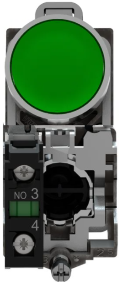
The START PUSH BUTTON (Manufacturer: Schneider, Part ID: XB4-BA31) is a momentary switch designed to complete an electrical circuit when pressed. It is commonly used to initiate functions or processes in electronic devices, industrial control systems, and automation equipment. This robust and reliable push button is ideal for applications requiring a durable and user-friendly interface.
Explore Projects Built with START PUSH BUTTON

Explore Projects Built with START PUSH BUTTON
Common Applications
- Industrial machinery start/stop controls
- Automation systems
- Control panels and operator interfaces
- DIY electronics projects
- Emergency or manual override systems
Technical Specifications
Key Technical Details
| Parameter | Specification |
|---|---|
| Manufacturer | Schneider |
| Part ID | XB4-BA31 |
| Switch Type | Momentary push button |
| Contact Configuration | Normally Open (NO) |
| Operating Voltage | Up to 600V AC/DC |
| Rated Current | 10A |
| Mechanical Durability | 1,000,000 cycles |
| Mounting Style | Panel mount (22mm diameter cutout) |
| Operating Temperature | -25°C to +70°C |
| Material | Metal bezel with plastic actuator |
| IP Rating | IP66 (dust-tight and water-resistant) |
Pin Configuration and Descriptions
The XB4-BA31 push button has a simple pin configuration, as shown below:
| Pin Label | Description |
|---|---|
| NO | Normally Open contact (output pin) |
| COM | Common terminal (input pin) |
When the button is pressed, the NO pin connects to the COM pin, completing the circuit.
Usage Instructions
How to Use the Component in a Circuit
Mounting the Button:
- Drill a 22mm diameter hole in the panel where the button will be installed.
- Insert the push button into the hole and secure it using the provided mounting hardware.
Wiring the Button:
- Connect the COM terminal to the positive voltage source or signal input.
- Connect the NO terminal to the load or the circuit that needs to be activated.
- Ensure all connections are secure and insulated to prevent short circuits.
Testing the Button:
- Power on the circuit and press the button to verify that it completes the circuit and activates the desired function.
Important Considerations and Best Practices
- Voltage and Current Ratings: Ensure the button is used within its rated voltage (up to 600V) and current (10A) limits to avoid damage.
- Debouncing: For digital circuits, implement a debouncing mechanism (hardware or software) to eliminate false triggers caused by mechanical bounce.
- Environmental Protection: The IP66 rating ensures protection against dust and water, but avoid submerging the button in water or exposing it to extreme conditions beyond its rated temperature range.
- Safety: Disconnect power before wiring or servicing the button to prevent electrical shock.
Example: Connecting to an Arduino UNO
The START PUSH BUTTON can be easily interfaced with an Arduino UNO for digital input. Below is an example circuit and code:
Circuit Diagram
- Connect the COM terminal to the Arduino's GND pin.
- Connect the NO terminal to a digital input pin (e.g., D2) on the Arduino.
- Use a pull-up resistor (10kΩ) between the digital input pin and 5V to ensure a stable signal.
Arduino Code
// Define the pin connected to the push button
const int buttonPin = 2;  // Digital pin 2 for button input

// Variable to store the button state
int buttonState = 0;

void setup() {
  pinMode(buttonPin, INPUT_PULLUP);  // Set button pin as input with internal pull-up
  Serial.begin(9600);               // Initialize serial communication
}

void loop() {
  // Read the button state (LOW when pressed, HIGH when released)
  buttonState = digitalRead(buttonPin);

  if (buttonState == LOW) {
    // Button is pressed
    Serial.println("Button Pressed!");
  } else {
    // Button is not pressed
    Serial.println("Button Released!");
  }

  delay(100);  // Small delay to avoid spamming the serial monitor
}
Troubleshooting and FAQs
Common Issues and Solutions
Button Not Responding:
- Cause: Loose or incorrect wiring.
- Solution: Double-check all connections and ensure the button is securely mounted.
Button Stuck in Pressed Position:
- Cause: Mechanical wear or debris in the button mechanism.
- Solution: Clean the button and ensure it is free of obstructions. Replace if necessary.
False Triggers in Digital Circuits:
- Cause: Mechanical bounce or lack of pull-up resistor.
- Solution: Implement a debouncing mechanism and use a pull-up resistor.
Button Fails in Harsh Environments:
- Cause: Exposure to conditions beyond the IP66 rating.
- Solution: Use additional protective enclosures or relocate the button to a safer environment.
FAQs
Q1: Can the XB4-BA31 be used for DC circuits?
A1: Yes, the button supports both AC and DC circuits up to 600V.
Q2: Is the button suitable for outdoor use?
A2: Yes, the IP66 rating ensures protection against dust and water, making it suitable for outdoor use in most conditions.
Q3: Can I use this button with a microcontroller other than Arduino?
A3: Absolutely! The button can be used with any microcontroller or logic circuit that accepts digital input.
Q4: How do I implement hardware debouncing?
A4: Add a small capacitor (e.g., 0.1µF) across the NO and COM terminals to smooth out mechanical bounce.
By following this documentation, you can effectively integrate the Schneider XB4-BA31 START PUSH BUTTON into your projects and systems.