How to Use Esp32 s3 super mini: Examples, Pinouts, and Specs
Introduction
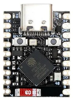
The ESP32 S3 Super Mini, manufactured by Arduino, is a compact and powerful microcontroller designed for Internet of Things (IoT) applications. It combines dual-core processing power with integrated Wi-Fi and Bluetooth connectivity, making it an excellent choice for smart devices, embedded systems, and wireless communication projects. Its small form factor and low power consumption make it ideal for portable and battery-powered applications.
Explore Projects Built with Esp32 s3 super mini


Explore Projects Built with Esp32 s3 super mini
Common Applications and Use Cases
- Smart home devices (e.g., smart lights, thermostats)
- Wearable technology
- Industrial IoT systems
- Wireless sensor networks
- Robotics and automation
- Prototyping and development of connected devices
Technical Specifications
The ESP32 S3 Super Mini offers a robust set of features to support a wide range of applications. Below are its key technical specifications:
| Specification | Details |
|---|---|
| Processor | Dual-core Xtensa® LX7, up to 240 MHz |
| Flash Memory | 8 MB (external) |
| RAM | 512 KB SRAM |
| Wireless Connectivity | Wi-Fi 802.11 b/g/n (2.4 GHz), Bluetooth 5.0 LE |
| GPIO Pins | 14 GPIO pins (configurable for digital, analog, I2C, SPI, UART, PWM, etc.) |
| Operating Voltage | 3.3V |
| Input Voltage Range | 5V (via USB-C) |
| Power Consumption | Ultra-low power modes available |
| Dimensions | 25 mm x 18 mm |
| Operating Temperature | -40°C to +85°C |
Pin Configuration and Descriptions
The ESP32 S3 Super Mini has a total of 14 GPIO pins, which can be configured for various functions. Below is the pinout description:
| Pin | Name | Function |
|---|---|---|
| 1 | GND | Ground |
| 2 | 3V3 | 3.3V Power Output |
| 3 | GPIO0 | General Purpose I/O, Boot Mode Selection |
| 4 | GPIO1 | General Purpose I/O, UART TX |
| 5 | GPIO2 | General Purpose I/O, UART RX |
| 6 | GPIO3 | General Purpose I/O, I2C SDA |
| 7 | GPIO4 | General Purpose I/O, I2C SCL |
| 8 | GPIO5 | General Purpose I/O, SPI MOSI |
| 9 | GPIO6 | General Purpose I/O, SPI MISO |
| 10 | GPIO7 | General Purpose I/O, SPI SCK |
| 11 | GPIO8 | General Purpose I/O, PWM Output |
| 12 | GPIO9 | General Purpose I/O, ADC Input |
| 13 | GPIO10 | General Purpose I/O, DAC Output |
| 14 | EN | Enable Pin (Active High) |
Usage Instructions
How to Use the ESP32 S3 Super Mini in a Circuit
Powering the Module:
- Use a USB-C cable to supply 5V to the module. The onboard voltage regulator will step it down to 3.3V.
- Alternatively, you can power the module directly via the 3V3 pin with a regulated 3.3V supply.
Connecting Peripherals:
- Use the GPIO pins to connect sensors, actuators, or other peripherals. Refer to the pin configuration table for specific pin functions.
- For communication protocols like I2C, SPI, or UART, ensure proper wiring and configuration in your code.
Programming the Module:
- The ESP32 S3 Super Mini can be programmed using the Arduino IDE. Install the ESP32 board package in the Arduino IDE to get started.
- Connect the module to your computer via USB-C and select the appropriate board and port in the IDE.
Important Considerations and Best Practices
- Voltage Levels: Ensure all connected peripherals operate at 3.3V logic levels to avoid damaging the module.
- Boot Mode: To enter bootloader mode for programming, hold down the GPIO0 pin (BOOT) while resetting the module.
- Antenna Placement: For optimal Wi-Fi and Bluetooth performance, avoid placing the module near metal objects or inside enclosures that block RF signals.
- Power Consumption: Use the ultra-low power modes for battery-powered applications to extend battery life.
Example Code for Arduino IDE
Below is an example code to connect the ESP32 S3 Super Mini to a Wi-Fi network and blink an LED:
#include <WiFi.h> // Include the Wi-Fi library

// Replace with your network credentials
const char* ssid = "Your_SSID";
const char* password = "Your_PASSWORD";

const int ledPin = GPIO8; // Define the LED pin (GPIO8)

void setup() {
  pinMode(ledPin, OUTPUT); // Set the LED pin as an output
  Serial.begin(115200);    // Start the serial communication

  // Connect to Wi-Fi
  Serial.print("Connecting to Wi-Fi");
  WiFi.begin(ssid, password);
  while (WiFi.status() != WL_CONNECTED) {
    delay(500);
    Serial.print(".");
  }
  Serial.println("\nConnected to Wi-Fi!");
}

void loop() {
  digitalWrite(ledPin, HIGH); // Turn the LED on
  delay(1000);                // Wait for 1 second
  digitalWrite(ledPin, LOW);  // Turn the LED off
  delay(1000);                // Wait for 1 second
}
Troubleshooting and FAQs
Common Issues and Solutions
Module Not Detected by Computer:
- Ensure the USB-C cable is properly connected and supports data transfer.
- Check if the correct port is selected in the Arduino IDE.
Wi-Fi Connection Fails:
- Double-check the SSID and password in your code.
- Ensure the Wi-Fi network is within range and operational.
GPIO Pins Not Responding:
- Verify that the pins are correctly configured in your code.
- Check for short circuits or incorrect wiring.
High Power Consumption:
- Use deep sleep or light sleep modes to reduce power usage.
- Disconnect unused peripherals to minimize current draw.
FAQs
Q: Can I use 5V peripherals with the ESP32 S3 Super Mini?
A: No, the GPIO pins operate at 3.3V logic levels. Use a level shifter if you need to interface with 5V devices.
Q: How do I reset the module?
A: Press the EN (Enable) pin to reset the module.
Q: Does the module support OTA (Over-the-Air) updates?
A: Yes, the ESP32 S3 Super Mini supports OTA updates. You can implement this feature in your code using the Arduino IDE or other development environments.
Q: What is the maximum Wi-Fi range?
A: The Wi-Fi range depends on environmental factors but typically extends up to 50 meters indoors and 200 meters outdoors in open spaces.