How to Use esp 32: Examples, Pinouts, and Specs
Introduction
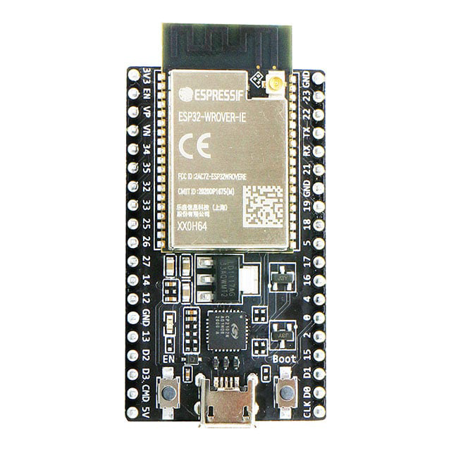
The ESP32, manufactured by Espressif Systems (Part ID: ESP32), is a low-cost, low-power system on a chip (SoC) designed for a wide range of applications. It features integrated Wi-Fi and Bluetooth capabilities, making it an ideal choice for Internet of Things (IoT) devices, smart home systems, wearable electronics, and embedded systems. Its versatility, robust performance, and extensive community support have made it a popular choice among hobbyists and professionals alike.
Explore Projects Built with esp 32


Explore Projects Built with esp 32
Common Applications and Use Cases
- IoT devices and smart home automation
- Wireless sensor networks
- Wearable electronics
- Industrial automation
- Robotics and drones
- Prototyping and educational projects
Technical Specifications
The ESP32 is a highly integrated SoC with the following key technical specifications:
| Parameter | Specification |
|---|---|
| Manufacturer | Espressif Systems |
| Part ID | ESP32 |
| CPU | Dual-core Xtensa® 32-bit LX6 microprocessor, up to 240 MHz |
| Wireless Connectivity | Wi-Fi 802.11 b/g/n, Bluetooth v4.2 BR/EDR and BLE |
| Flash Memory | 4 MB (varies by module) |
| SRAM | 520 KB |
| GPIO Pins | Up to 34 GPIO pins |
| Operating Voltage | 3.0V to 3.6V |
| Power Consumption | Ultra-low power consumption with multiple power modes |
| Interfaces | UART, SPI, I2C, I2S, PWM, ADC (12-bit), DAC (8-bit), Ethernet MAC, SDIO, CAN |
| Operating Temperature | -40°C to +85°C |
| Dimensions | Varies by module (e.g., ESP32-WROOM-32: 18mm x 25.5mm) |
Pin Configuration and Descriptions
The ESP32 has a flexible pinout, with up to 34 GPIO pins. Below is a table of commonly used pins and their functions:
| Pin Name | Function |
|---|---|
| GPIO0 | Boot mode selection, general-purpose I/O |
| GPIO1 (TXD0) | UART0 transmit |
| GPIO3 (RXD0) | UART0 receive |
| GPIO12 | HSPI MISO, ADC2 channel, general-purpose I/O |
| GPIO13 | HSPI MOSI, ADC2 channel, general-purpose I/O |
| GPIO14 | HSPI CLK, ADC2 channel, general-purpose I/O |
| GPIO15 | HSPI CS, ADC2 channel, general-purpose I/O |
| GPIO16 | General-purpose I/O |
| GPIO17 | General-purpose I/O |
| GPIO21 | I2C SDA, general-purpose I/O |
| GPIO22 | I2C SCL, general-purpose I/O |
| GPIO23 | VSPI MOSI, general-purpose I/O |
| GPIO25 | DAC1, ADC2 channel, general-purpose I/O |
| GPIO26 | DAC2, ADC2 channel, general-purpose I/O |
| GPIO27 | ADC2 channel, general-purpose I/O |
| GPIO32 | ADC1 channel, touch sensor, general-purpose I/O |
| GPIO33 | ADC1 channel, touch sensor, general-purpose I/O |
| GPIO34 | ADC1 channel (input only) |
| GPIO35 | ADC1 channel (input only) |
| GPIO36 | ADC1 channel (input only) |
| GPIO39 | ADC1 channel (input only) |
Note: Not all GPIO pins support all functions simultaneously. Refer to the ESP32 datasheet for detailed pin multiplexing information.
Usage Instructions
The ESP32 can be used in a variety of circuits and applications. Below are the steps to get started with the ESP32:
1. Setting Up the Development Environment
- Download and install the Arduino IDE (or use Espressif's ESP-IDF for advanced development).
- Install the ESP32 board package in the Arduino IDE:
- Go to File > Preferences and add the following URL to the "Additional Board Manager URLs" field:
https://dl.espressif.com/dl/package_esp32_index.json - Open Tools > Board > Boards Manager, search for "ESP32," and install the package.
- Go to File > Preferences and add the following URL to the "Additional Board Manager URLs" field:
2. Connecting the ESP32 to Your Computer
- Use a USB-to-micro-USB cable to connect the ESP32 to your computer.
- Select the correct board and port in the Arduino IDE:
- Board: Select your ESP32 module (e.g., "ESP32 Dev Module").
- Port: Select the COM port associated with the ESP32.
3. Writing and Uploading Code
Below is an example code to blink an LED connected to GPIO2:
// Example: Blink an LED connected to GPIO2 on the ESP32

#define LED_PIN 2  // Define the GPIO pin for the LED

void setup() {
  pinMode(LED_PIN, OUTPUT);  // Set GPIO2 as an output pin
}

void loop() {
  digitalWrite(LED_PIN, HIGH);  // Turn the LED on
  delay(1000);                  // Wait for 1 second
  digitalWrite(LED_PIN, LOW);   // Turn the LED off
  delay(1000);                  // Wait for 1 second
}
4. Important Considerations and Best Practices
- Power Supply: Ensure the ESP32 is powered with a stable 3.3V supply. Avoid exceeding 3.6V.
- Boot Mode: GPIO0 must be pulled low during boot to enter flash mode.
- GPIO Limitations: Some GPIO pins have specific restrictions (e.g., GPIO34-39 are input-only).
- Wi-Fi and Bluetooth: Avoid using ADC2 channels when Wi-Fi is active, as they share resources.
Troubleshooting and FAQs
Common Issues and Solutions
ESP32 Not Detected by Computer:
- Ensure the USB cable is functional and supports data transfer.
- Install the correct USB-to-serial driver (e.g., CP210x or CH340).
Upload Fails with "Failed to Connect" Error:
- Press and hold the "BOOT" button on the ESP32 while uploading the code.
- Check the COM port and board settings in the Arduino IDE.
Wi-Fi Connection Issues:
- Verify the SSID and password in your code.
- Ensure the Wi-Fi network is within range and supports 2.4 GHz (ESP32 does not support 5 GHz).
Random Resets or Instability:
- Check the power supply for sufficient current (at least 500 mA).
- Add decoupling capacitors near the ESP32's power pins.
FAQs
Q: Can the ESP32 run on battery power?
A: Yes, the ESP32 supports low-power modes, making it suitable for battery-powered applications. Use a 3.7V LiPo battery with a voltage regulator to provide 3.3V.
Q: How do I use the ESP32's Bluetooth functionality?
A: The ESP32 supports both Bluetooth Classic and BLE. Use the BluetoothSerial library for Bluetooth Classic or the BLE library for BLE in the Arduino IDE.
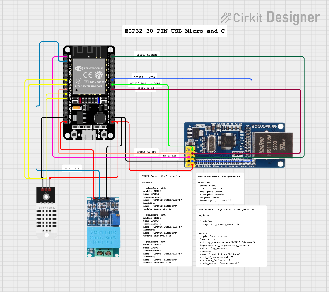
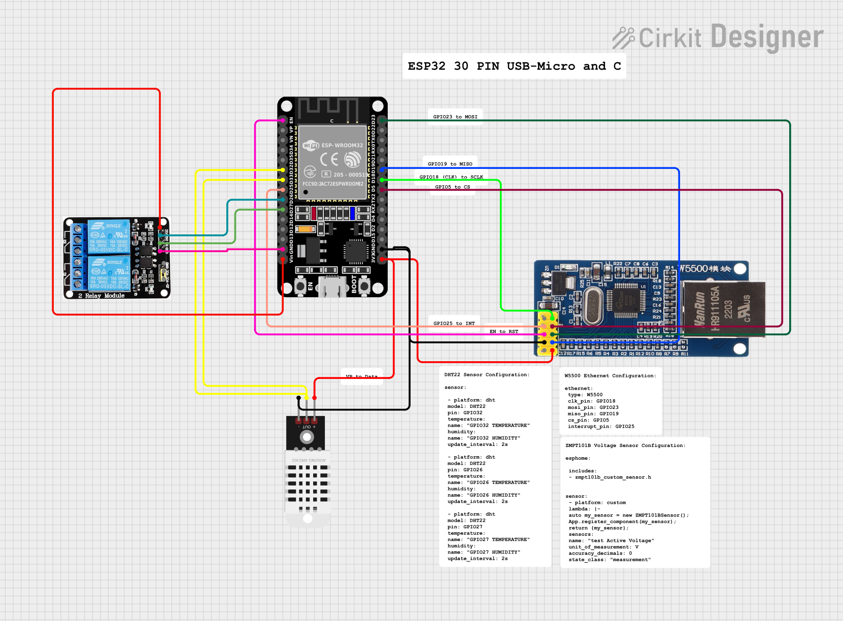
Q: Can I use the ESP32 with sensors and modules?
A: Yes, the ESP32 supports a wide range of sensors and modules via I2C, SPI, UART, and other interfaces.
Q: What is the maximum Wi-Fi range of the ESP32?
A: The ESP32's Wi-Fi range is approximately 50 meters indoors and 200 meters outdoors, depending on environmental factors.
By following this documentation, you can effectively utilize the ESP32 in your projects and troubleshoot common issues.