Cirkit Designer Logo
Cirkit Designer
Your all-in-one circuit design IDE
Home / 
Component Documentation

How to Use 12v SMPS Module: Examples, Pinouts, and Specs

Image of 12v SMPS Module
Cirkit Designer LogoDesign with 12v SMPS Module in Cirkit Designer

Introduction

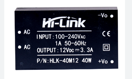
The 12V SMPS (Switched Mode Power Supply) module is a highly efficient power converter that provides a stable and regulated 12V DC output from a wider range of input voltages. This electronic component is commonly used in a variety of applications, including LED lighting systems, computer peripherals, telecommunications equipment, and consumer electronics where a reliable 12V power source is required.

Explore Projects Built with 12v SMPS Module

Use Cirkit Designer to design, explore, and prototype these projects online. Some projects support real-time simulation. Click "Open Project" to start designing instantly!
12V UPS System with Dual 18650 Li-ion Battery Backup and Voltage Regulation
Image of Power supply: A project utilizing 12v SMPS Module in a practical application
This circuit is designed to provide an uninterruptible power supply (UPS) system with a 12V DC output. It includes a 12V 5A power supply connected to an AC source through a toggle switch, which charges a pair of 18650 Li-ion batteries via a voltage regulator (XL4016). The UPS module ensures a continuous power supply to the load by switching between the power supply and the battery bank.
Cirkit Designer LogoOpen Project in Cirkit Designer
Modular Power Distribution System with Multiple SMPS Units and 120V Outlet
Image of Cellion-Tesla: A project utilizing 12v SMPS Module in a practical application
This circuit is designed to convert 240V AC power to both 12V and 24V DC outputs using multiple SMPS units. Terminal blocks are used to organize and distribute the power, while a 120V outlet provides additional AC power access. The circuit is likely used for powering various electronic devices that require different voltage levels.
Cirkit Designer LogoOpen Project in Cirkit Designer
Battery-Powered DC-DC Converter System for Multi-Voltage Power Distribution
Image of test 1 ih: A project utilizing 12v SMPS Module in a practical application
This circuit converts a 38.5V battery output to multiple lower voltage levels using a series of DC-DC converters and a power module. It includes an emergency stop switch for safety and distributes power to various components such as a relay module, USB ports, and a bus servo adaptor.
Cirkit Designer LogoOpen Project in Cirkit Designer
Battery-Powered Servo Control System with 2S 30A BMS and TP5100 Charger
Image of servo power supply: A project utilizing 12v SMPS Module in a practical application
This circuit is a battery management and charging system for a 2S lithium-ion battery pack, which powers multiple MG996R servos. The TP5100 module charges the battery pack from a 12V power supply, while the 2S 30A BMS ensures safe operation and distribution of power to the servos.
Cirkit Designer LogoOpen Project in Cirkit Designer

Explore Projects Built with 12v SMPS Module

Use Cirkit Designer to design, explore, and prototype these projects online. Some projects support real-time simulation. Click "Open Project" to start designing instantly!
Image of Power supply: A project utilizing 12v SMPS Module in a practical application
12V UPS System with Dual 18650 Li-ion Battery Backup and Voltage Regulation
This circuit is designed to provide an uninterruptible power supply (UPS) system with a 12V DC output. It includes a 12V 5A power supply connected to an AC source through a toggle switch, which charges a pair of 18650 Li-ion batteries via a voltage regulator (XL4016). The UPS module ensures a continuous power supply to the load by switching between the power supply and the battery bank.
Cirkit Designer LogoOpen Project in Cirkit Designer
Image of Cellion-Tesla: A project utilizing 12v SMPS Module in a practical application
Modular Power Distribution System with Multiple SMPS Units and 120V Outlet
This circuit is designed to convert 240V AC power to both 12V and 24V DC outputs using multiple SMPS units. Terminal blocks are used to organize and distribute the power, while a 120V outlet provides additional AC power access. The circuit is likely used for powering various electronic devices that require different voltage levels.
Cirkit Designer LogoOpen Project in Cirkit Designer
Image of test 1 ih: A project utilizing 12v SMPS Module in a practical application
Battery-Powered DC-DC Converter System for Multi-Voltage Power Distribution
This circuit converts a 38.5V battery output to multiple lower voltage levels using a series of DC-DC converters and a power module. It includes an emergency stop switch for safety and distributes power to various components such as a relay module, USB ports, and a bus servo adaptor.
Cirkit Designer LogoOpen Project in Cirkit Designer
Image of servo power supply: A project utilizing 12v SMPS Module in a practical application
Battery-Powered Servo Control System with 2S 30A BMS and TP5100 Charger
This circuit is a battery management and charging system for a 2S lithium-ion battery pack, which powers multiple MG996R servos. The TP5100 module charges the battery pack from a 12V power supply, while the 2S 30A BMS ensures safe operation and distribution of power to the servos.
Cirkit Designer LogoOpen Project in Cirkit Designer

Common Applications and Use Cases

  • Powering 12V LED strips and modules
  • Supplying power to 12V DC motors
  • Operating relays and solenoids in automation systems
  • Providing power for 12V electronic circuits
  • Used in battery charging and backup systems

Technical Specifications

Key Technical Details

  • Input Voltage Range: 100V AC to 240V AC
  • Output Voltage: 12V DC
  • Output Current: Varies by model (e.g., 1A, 2A, 5A)
  • Output Power: Varies by model (e.g., 12W, 24W, 60W)
  • Efficiency: >85%
  • Ripple & Noise: <120mV p-p
  • Protection: Overload, Short Circuit, Over Voltage

Pin Configuration and Descriptions

Pin No. Description Notes
1 AC Input L (Live) Connect to the live AC wire
2 AC Input N (Neutral) Connect to the neutral AC wire
3 Ground Connect to earth ground if available
4 DC Output +12V Positive output terminal
5 DC Output GND Ground reference for output

Usage Instructions

How to Use the Component in a Circuit

  1. Connecting AC Input:

    • Ensure the AC mains power is switched off before wiring.
    • Connect the live (L) and neutral (N) wires to the respective input pins.
    • If available, connect the ground wire to the ground pin for safety.
  2. Connecting DC Output:

    • Connect the positive output terminal to the positive input of your device or circuit.
    • Connect the ground terminal to the ground of your device or circuit.

Important Considerations and Best Practices

  • Verify the input voltage range compatibility before connecting to AC mains.
  • Ensure the output current and power ratings meet the requirements of your application.
  • Do not exceed the maximum ratings as it may lead to overheating or damage.
  • Use proper insulation on all AC connections to prevent accidental contact.
  • Place the SMPS in a ventilated area to prevent overheating.
  • If integrating with sensitive electronics, additional filtering may be necessary to reduce ripple and noise.

Troubleshooting and FAQs

Common Issues Users Might Face

  • No Output Voltage:

    • Check AC mains connection for proper voltage and polarity.
    • Verify that the SMPS is not in a protection mode due to overload or short circuit.
  • Output Voltage Fluctuations:

    • Ensure that the load does not exceed the rated current of the SMPS.
    • Check for loose connections or poor contacts at the output terminals.
  • Overheating:

    • Confirm that the ambient temperature is within the specified range.
    • Check for adequate ventilation around the SMPS module.

Solutions and Tips for Troubleshooting

  • If the SMPS enters protection mode, disconnect the load, check for shorts, and then restart the power supply.
  • Use a multimeter to measure the output voltage and ensure it is within the specified range.
  • For persistent noise or ripple issues, consider adding a capacitor across the output terminals for additional filtering.

FAQs

Q: Can I adjust the output voltage of the SMPS? A: Most 12V SMPS modules have a fixed output voltage. However, some models may include a potentiometer for fine adjustments.

Q: Is it safe to use the SMPS without a ground connection? A: While the SMPS can operate without a ground connection, it is recommended to connect the ground pin to earth ground for safety and noise reduction.

Q: How do I know if my SMPS can handle the load? A: Calculate the total power consumption of your load and ensure it does not exceed the power rating of the SMPS.

Q: What should I do if the SMPS is making a noise? A: Some noise can be normal, but excessive noise may indicate an overload or a failing component. Reduce the load and check the SMPS for any visible damage.


Note: This documentation is provided for informational purposes only. Always consult the specific datasheet and safety guidelines for the SMPS module you are using.