How to Use IRF710-TO220: Examples, Pinouts, and Specs
Introduction
The IRF710 is an N-channel MOSFET (Metal-Oxide-Semiconductor Field-Effect Transistor) designed for high-speed switching applications. It is housed in a TO-220 package, which provides excellent thermal performance and ease of mounting. This component is widely used in power electronics due to its ability to handle high voltages and currents efficiently.
Explore Projects Built with IRF710-TO220


Explore Projects Built with IRF710-TO220
Common Applications
- Motor control circuits
- DC-DC converters
- Power supply circuits
- High-speed switching applications
- LED drivers
Technical Specifications
Key Specifications
| Parameter | Value |
|---|---|
| Drain-Source Voltage (VDS) | 400 V |
| Continuous Drain Current (ID) | 2.9 A |
| Pulsed Drain Current (IDM) | 11.6 A |
| Gate-Source Voltage (VGS) | ±20 V |
| Power Dissipation (PD) | 50 W |
| RDS(on) (Max) | 3.5 Ω |
| Gate Threshold Voltage (VGS(th)) | 2.0 - 4.0 V |
| Maximum Operating Temperature | 150°C |
| Package Type | TO-220 |
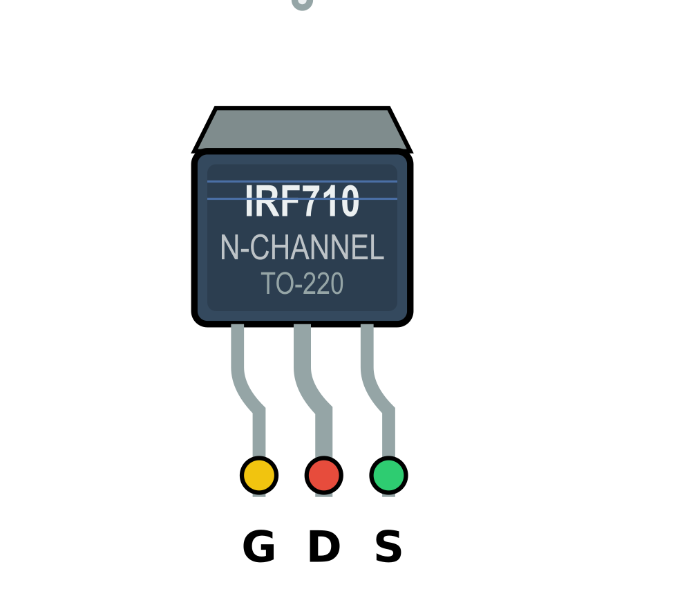
Pin Configuration
The IRF710 has three pins, as described in the table below:
| Pin Number | Pin Name | Description |
|---|---|---|
| 1 | Gate | Controls the MOSFET switching state |
| 2 | Drain | Current flows from drain to source |
| 3 | Source | Connected to ground or load return |
Usage Instructions
Using the IRF710 in a Circuit
- Gate Control: Apply a voltage between the Gate and Source (VGS) to control the MOSFET. A voltage above the threshold (typically 2-4 V) will turn the MOSFET on.
- Drain-Source Path: Connect the load between the Drain and the positive supply voltage. The Source is typically connected to ground.
- Heat Dissipation: Use a heatsink with the TO-220 package to ensure proper thermal management, especially in high-power applications.
- Gate Resistor: Add a resistor (typically 10-100 Ω) in series with the Gate to limit inrush current and prevent damage to the MOSFET.
- Flyback Diode: For inductive loads (e.g., motors), include a flyback diode across the load to protect the MOSFET from voltage spikes.
Example: Controlling an LED with Arduino UNO
Below is an example of how to use the IRF710 to control an LED with an Arduino UNO:
// Define the pin connected to the MOSFET Gate
const int mosfetGatePin = 9;

void setup() {
  pinMode(mosfetGatePin, OUTPUT); // Set the Gate pin as an output
}

void loop() {
  digitalWrite(mosfetGatePin, HIGH); // Turn the MOSFET on (LED ON)
  delay(1000);                       // Wait for 1 second
  digitalWrite(mosfetGatePin, LOW);  // Turn the MOSFET off (LED OFF)
  delay(1000);                       // Wait for 1 second
}
Circuit Connections:
- Connect the Gate pin of the IRF710 to Arduino pin 9 through a 100 Ω resistor.
- Connect the Source pin to ground.
- Connect the LED and a current-limiting resistor in series between the Drain pin and the positive supply voltage.
Important Considerations
- Ensure the Gate-Source voltage does not exceed ±20 V to avoid damaging the MOSFET.
- Use a heatsink for applications where the power dissipation exceeds 1-2 W.
- Avoid exceeding the maximum Drain-Source voltage (400 V) or Drain current (2.9 A continuous).
Troubleshooting and FAQs
Common Issues and Solutions
MOSFET Not Turning On:
- Ensure the Gate-Source voltage (VGS) is above the threshold voltage (2-4 V).
- Check for a proper connection between the Gate and the control signal.
Excessive Heat:
- Verify that a heatsink is installed and properly attached to the TO-220 package.
- Ensure the MOSFET is operating within its power dissipation limits.
MOSFET Fails to Switch Off:
- Check for residual voltage on the Gate. Add a pull-down resistor (10 kΩ) between the Gate and Source to ensure proper discharge.
Voltage Spikes Damaging the MOSFET:
- For inductive loads, ensure a flyback diode is installed across the load to suppress voltage spikes.
FAQs
Q: Can the IRF710 be used for low-voltage applications?
A: Yes, but it is optimized for high-voltage applications. For low-voltage circuits, consider using a MOSFET with a lower RDS(on) for better efficiency.
Q: What is the maximum PWM frequency for the IRF710?
A: The IRF710 can handle high-speed switching, but the exact frequency depends on the Gate drive circuit. Typically, it can operate in the range of tens to hundreds of kHz.
Q: Do I need a heatsink for low-power applications?
A: A heatsink is not necessary if the power dissipation is minimal (e.g., less than 1 W). However, for higher power levels, a heatsink is recommended.
Q: Can I drive the IRF710 directly from an Arduino?
A: Yes, the IRF710 can be driven directly from an Arduino pin, as long as the Gate-Source voltage is within the required range (2-4 V for switching). However, adding a Gate resistor is recommended for protection.