How to Use RS422-to-TTL module: Examples, Pinouts, and Specs
Introduction
The RS422-to-TTL module is a device designed to convert RS422 differential signals into TTL (Transistor-Transistor Logic) levels. RS422 is a robust communication standard commonly used in industrial and long-distance data transmission applications, while TTL is a logic level standard used in microcontrollers and digital circuits. This module bridges the gap between these two standards, enabling seamless communication between devices that operate on different signaling levels.
Explore Projects Built with RS422-to-TTL module


Explore Projects Built with RS422-to-TTL module
Common Applications and Use Cases
- Interfacing industrial RS422 devices with microcontrollers (e.g., Arduino, Raspberry Pi).
- Converting RS422 signals for use in TTL-based digital circuits.
- Data acquisition systems requiring RS422-to-TTL signal conversion.
- Communication between RS422-enabled sensors and TTL-based processors.
- Robotics and automation systems requiring mixed-signal communication.
Technical Specifications
Key Technical Details
- Input Signal Standard: RS422 differential signals.
- Output Signal Standard: TTL logic levels (0V to 5V).
- Operating Voltage: 3.3V to 5V DC.
- Baud Rate: Up to 1 Mbps (depending on cable length and quality).
- Input Impedance: 120Ω (typical for RS422 termination).
- Operating Temperature: -40°C to 85°C.
- Dimensions: Compact PCB module, typically 25mm x 15mm.
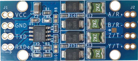
Pin Configuration and Descriptions
The RS422-to-TTL module typically has the following pin configuration:
| Pin Name | Type | Description |
|---|---|---|
| VCC | Power Input | Power supply input (3.3V to 5V DC). |
| GND | Power Ground | Ground connection for the module. |
| A (RS422+) | Input | Positive differential input signal from the RS422 device. |
| B (RS422-) | Input | Negative differential input signal from the RS422 device. |
| RXD | Output | TTL-level received data output (to be connected to the microcontroller RX pin). |
| TXD | Input | TTL-level transmit data input (from the microcontroller TX pin). |
Usage Instructions
How to Use the Component in a Circuit
- Power the Module: Connect the VCC pin to a 3.3V or 5V power source and the GND pin to the ground of your circuit.
- Connect RS422 Signals: Attach the RS422 differential signal lines to the A (RS422+) and B (RS422-) pins of the module.
- Connect TTL Signals:
- Connect the RXD pin of the module to the RX pin of your microcontroller or TTL device.
- Connect the TXD pin of your microcontroller or TTL device to the TXD pin of the module.
- Termination Resistor: If the RS422 line is not already terminated, add a 120Ω resistor across the A and B pins to ensure proper signal integrity.
- Test Communication: Verify the communication by sending and receiving data between the RS422 device and the TTL device.
Important Considerations and Best Practices
- Ensure that the power supply voltage matches the module's operating range (3.3V to 5V).
- Use shielded twisted-pair cables for RS422 connections to minimize noise and interference.
- Keep the RS422 cable length within the standard's limits (up to 1200 meters) for reliable communication.
- Verify the baud rate settings of both the RS422 device and the TTL device to ensure compatibility.
- Avoid connecting the module to RS485 devices unless the protocol and signaling are compatible.
Example: Connecting to an Arduino UNO
Below is an example of how to use the RS422-to-TTL module with an Arduino UNO to receive data from an RS422 device.
Circuit Diagram
- Connect the module's VCC and GND to the Arduino's 5V and GND pins, respectively.
- Connect the RXD pin of the module to the Arduino's digital pin 0 (RX).
- Connect the TXD pin of the Arduino (digital pin 1) to the TXD pin of the module.
- Connect the RS422 device's A and B lines to the module's A and B pins.
Arduino Code Example
// RS422-to-TTL Module Example Code
// This code reads data from an RS422 device and prints it to the Serial Monitor.

void setup() {
  Serial.begin(9600); // Initialize serial communication at 9600 baud
  Serial.println("RS422-to-TTL Module Test");
}

void loop() {
  // Check if data is available from the RS422 device
  if (Serial.available() > 0) {
    char receivedData = Serial.read(); // Read one byte of data
    Serial.print("Received: ");        // Print the received data
    Serial.println(receivedData);
  }
}
Troubleshooting and FAQs
Common Issues and Solutions
No Data Received on TTL Side:
- Verify the RS422 device is powered and transmitting data.
- Check the connections between the RS422 device and the module (A to A, B to B).
- Ensure the baud rate settings match between the RS422 device and the TTL device.
Corrupted or Noisy Data:
- Use shielded twisted-pair cables for RS422 connections.
- Add a 120Ω termination resistor across the A and B pins if not already present.
- Ensure the RS422 cable length is within the standard's limits.
Module Overheating:
- Check the power supply voltage; it should not exceed 5V.
- Ensure proper ventilation around the module.
RS422 Device Not Responding:
- Confirm the RS422 device is configured for communication.
- Verify the polarity of the A and B connections; swapping them may resolve the issue.
FAQs
Q1: Can this module be used with RS485 devices?
A1: While RS422 and RS485 share similarities, this module is specifically designed for RS422 signals. Ensure compatibility before attempting to use it with RS485 devices.
Q2: What is the maximum baud rate supported by the module?
A2: The module supports baud rates up to 1 Mbps, but the actual performance depends on cable length and quality.
Q3: Can I use this module with a 3.3V microcontroller?
A3: Yes, the module is compatible with both 3.3V and 5V systems. Ensure the VCC pin is connected to the appropriate voltage.
Q4: Do I need to add a termination resistor?
A4: If the RS422 line is not already terminated, you should add a 120Ω resistor across the A and B pins for proper signal integrity.