How to Use ESP32 ESP32S 30P Expansion Board: Examples, Pinouts, and Specs
Introduction
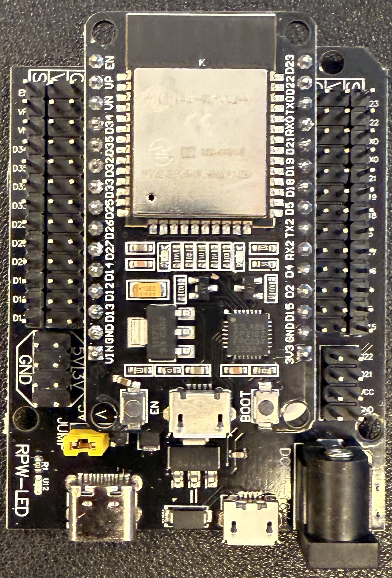
The ESP32 ESP32S 30P Expansion Board is a versatile and powerful microcontroller board that integrates an ESP32S module, offering a wide range of features including Wi-Fi and Bluetooth connectivity. This board is designed to provide an easy way to interface with various sensors, actuators, and other electronic components, making it an ideal choice for IoT projects, home automation, and prototyping.
Explore Projects Built with ESP32 ESP32S 30P Expansion Board
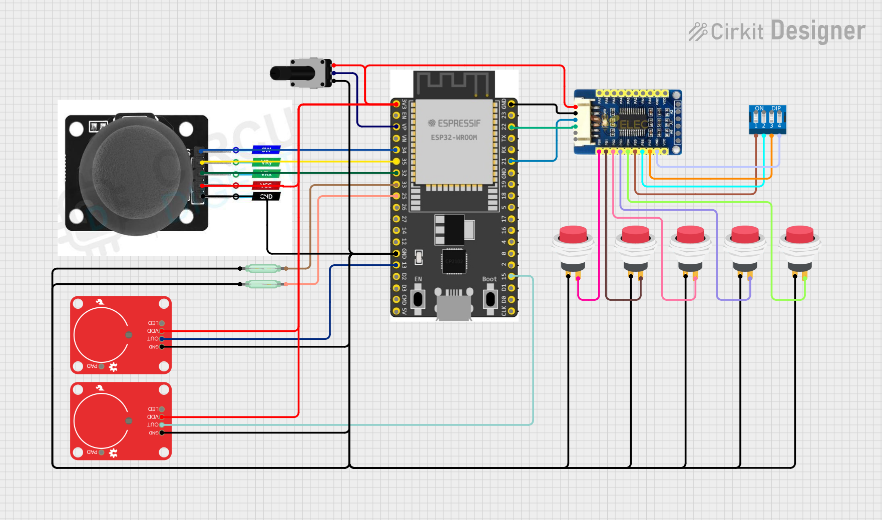
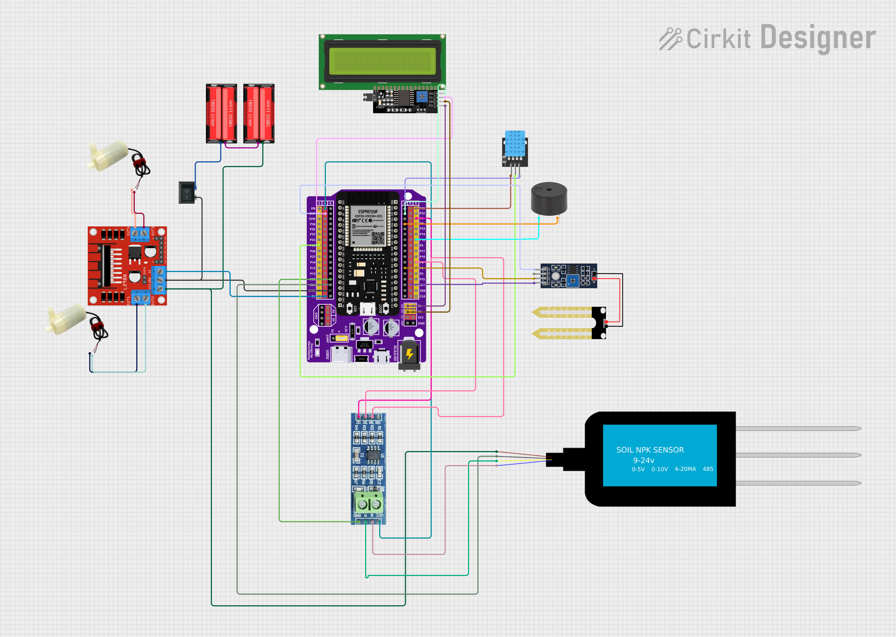


Explore Projects Built with ESP32 ESP32S 30P Expansion Board
Common Applications and Use Cases
- Internet of Things (IoT) devices
- Home automation systems
- Wireless sensor networks
- DIY electronics projects
- Prototyping for embedded systems
Technical Specifications
Key Technical Details
- Microcontroller: ESP32S
- Operating Voltage: 3.3V
- Input Voltage (recommended): 5V via micro USB
- Digital I/O Pins: 22
- Analog Input Pins: 6 (VP, VN, 32, 33, 34, 35)
- Flash Memory: 4MB
- SRAM: 520 KB
- Clock Speed: 240 MHz
- Wi-Fi: 802.11 b/g/n
- Bluetooth: v4.2 BR/EDR and BLE
- Operating Temperature: -40°C to +125°C
Pin Configuration and Descriptions
| Pin Number | Function | Description |
|---|---|---|
| 1-30 | GPIO/Power/Control | Multiple GPIO and power pins for various functions |
Note: The exact pinout may vary depending on the manufacturer. Please refer to the specific datasheet provided by the manufacturer for detailed pin descriptions.
Usage Instructions
How to Use the Component in a Circuit
Powering the Board:
- Connect a 5V power supply to the VIN and GND pins or use the micro USB port.
Connecting to Wi-Fi:
- Utilize the onboard Wi-Fi capabilities to connect to a network for IoT applications.
Interfacing with Sensors/Actuators:
- Connect sensors to the analog pins for data acquisition.
- Use the digital pins to control actuators like motors or LEDs.
Important Considerations and Best Practices
- Ensure that the input voltage does not exceed the recommended 5V to prevent damage.
- Use a current limiting resistor when connecting LEDs to GPIO pins.
- When using Wi-Fi or Bluetooth, consider the power consumption and plan your power supply accordingly.
- Avoid placing the board in environments that exceed the operating temperature range.
- Always disconnect the board from power before making or altering connections.
Troubleshooting and FAQs
Common Issues
- Board not powering up: Check the power supply and connections to ensure proper voltage and polarity.
- Wi-Fi/Bluetooth not functioning: Verify that the antenna is properly connected and that there are no obstructions.
- Inconsistent readings from sensors: Ensure that the sensor is correctly wired and that the code is properly calibrated.
Solutions and Tips for Troubleshooting
- Double-check wiring against the board's pinout diagram.
- Use serial output to debug and monitor the status of the board.
- Update the firmware of the ESP32S module to the latest version.
- Consult online forums and communities for support specific to the ESP32S module.
FAQs
Q: Can the ESP32 ESP32S 30P Expansion Board be programmed using the Arduino IDE?
A: Yes, the board can be programmed using the Arduino IDE after installing the appropriate ESP32 board package.
Q: Does the board have onboard battery management?
A: This depends on the specific design of the expansion board. Some may include battery charging and management circuits, while others may not.
Q: How many GPIO pins support PWM?
A: Most of the digital pins on the ESP32 support PWM. Check the ESP32 datasheet for the exact number and their capabilities.
Q: What is the maximum current that can be drawn from a single GPIO pin?
A: Typically, the maximum current per GPIO pin should not exceed 12 mA. Refer to the ESP32 datasheet for precise limits.
Example Code for Arduino UNO
// Ensure you have the ESP32 board package installed in your Arduino IDE
#include <WiFi.h>

const char* ssid = "yourSSID"; // Replace with your Wi-Fi SSID
const char* password = "yourPASSWORD"; // Replace with your Wi-Fi password

void setup() {
  Serial.begin(115200);
  // Connect to Wi-Fi
  WiFi.begin(ssid, password);
  while (WiFi.status() != WL_CONNECTED) {
    delay(500);
    Serial.println("Connecting to WiFi...");
  }
  Serial.println("Connected to WiFi");
}

void loop() {
  // Your main code would go here
}
Note: This code is a basic example to connect the ESP32 to Wi-Fi. For specific applications, the code will need to be modified accordingly.
Remember to keep your Wi-Fi credentials private and secure. This example is for demonstration purposes only and should be adapted with security best practices in mind.