
How to Use Receiver Elrs 2.4Ghz: Examples, Pinouts, and Specs
 Design with Receiver Elrs 2.4Ghz in Cirkit Designer
Introduction
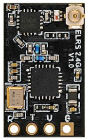
The Betafpv RX ELRS is a 2.4 GHz receiver designed for low-latency and high-performance communication in remote control applications. It is part of the ExpressLRS (ELRS) ecosystem, which is known for its open-source firmware and exceptional range and reliability. This receiver is commonly used in drones, RC vehicles, and other remote-controlled systems where precise and responsive control is critical.
Explore Projects Built with Receiver Elrs 2.4Ghz
 Open Project in Cirkit Designer
 Open Project in Cirkit Designer
 Open Project in Cirkit Designer
 Open Project in Cirkit Designer
Explore Projects Built with Receiver Elrs 2.4Ghz
Open Project in Cirkit DesignerOpen Project in Cirkit DesignerOpen Project in Cirkit DesignerOpen Project in Cirkit DesignerCommon Applications
- FPV (First-Person View) drones for racing and freestyle
- RC cars, boats, and planes
- Robotics and automation systems requiring wireless control
- Long-range telemetry and control systems
Technical Specifications
The following table outlines the key technical details of the Betafpv RX ELRS 2.4GHz receiver:
| Parameter | Specification |
|---|---|
| Operating Frequency | 2.4 GHz |
| Protocol | ExpressLRS (ELRS) |
| Input Voltage Range | 5V (via UART or dedicated power source) |
| Antenna Type | External, IPEX connector |
| Latency | Ultra-low (as low as 4ms) |
| Dimensions | 10mm x 10mm x 2mm |
| Weight | ~0.5g |
| Firmware Compatibility | ExpressLRS open-source firmware |
| Binding Method | ELRS binding phrase or manual bind button |
Pin Configuration
The RX ELRS receiver has a simple pinout for easy integration into your system. Below is the pin configuration:
| Pin Name | Description |
|---|---|
| GND | Ground connection |
| 5V | Power input (5V) |
| TX | UART Transmit (to flight controller or MCU RX pin) |
| RX | UART Receive (to flight controller or MCU TX pin) |
Usage Instructions
How to Use the RX ELRS Receiver in a Circuit
- Power Connection: Connect the 5V pin to a regulated 5V power source and the GND pin to the ground of your system.
- UART Connection: Connect the TX pin of the receiver to the RX pin of your flight controller or microcontroller. Similarly, connect the RX pin of the receiver to the TX pin of your flight controller or microcontroller.
- Antenna Installation: Attach the external antenna to the IPEX connector. Ensure the antenna is securely connected to avoid signal loss.
- Binding:
- If using a binding phrase, ensure the same phrase is configured in both the transmitter and receiver firmware.
- For manual binding, press and hold the bind button on the receiver while powering it on. Follow the transmitter's binding procedure to complete the process.
Important Considerations
- Firmware Updates: Ensure the receiver firmware matches the version of your transmitter firmware for compatibility.
- Antenna Placement: Position the antenna away from metal components or other RF sources to minimize interference.
- Voltage Regulation: Use a stable 5V power source to avoid damaging the receiver.
- UART Configuration: Configure the UART port on your flight controller or microcontroller to match the baud rate specified in the ELRS firmware.
Example Code for Arduino UNO
The RX ELRS receiver can be connected to an Arduino UNO for basic communication. Below is an example code snippet to read data from the receiver:
#include <SoftwareSerial.h>

// Define RX and TX pins for the receiver
#define RX_PIN 10  // Connect to the TX pin of the receiver
#define TX_PIN 11  // Connect to the RX pin of the receiver

// Initialize SoftwareSerial for communication
SoftwareSerial elrsSerial(RX_PIN, TX_PIN);

void setup() {
  // Start serial communication with the receiver
  Serial.begin(9600); // Monitor output
  elrsSerial.begin(115200); // ELRS receiver baud rate

  Serial.println("ELRS Receiver Initialized");
}

void loop() {
  // Check if data is available from the receiver
  if (elrsSerial.available()) {
    // Read and print the received data
    char receivedData = elrsSerial.read();
    Serial.print("Received: ");
    Serial.println(receivedData);
  }
}
Notes:
- Replace
115200with the baud rate configured in your ELRS firmware if different. - Ensure the RX and TX pins are correctly connected to the receiver.
Troubleshooting and FAQs
Common Issues and Solutions
Receiver Not Binding to Transmitter
- Ensure the binding phrase matches between the transmitter and receiver firmware.
- Check that the receiver is in binding mode (bind button pressed during power-up).
- Verify that the transmitter is set to the correct frequency and protocol.
No Signal or Poor Range
- Ensure the antenna is securely connected and properly positioned.
- Avoid placing the receiver near metal components or other RF sources.
- Check for firmware mismatches between the transmitter and receiver.
Receiver Not Powering On
- Verify that the 5V power source is stable and correctly connected.
- Check for loose or damaged wires.
Data Not Received by Microcontroller
- Confirm that the UART connections (TX and RX) are correctly wired.
- Ensure the baud rate in the microcontroller matches the receiver's configuration.
FAQs
Q: Can I use the RX ELRS receiver with other transmitters?
A: Yes, the RX ELRS receiver is compatible with any transmitter running ExpressLRS firmware, provided the firmware versions match.
Q: What is the maximum range of the RX ELRS receiver?
A: The range depends on the transmitter power and antenna setup but can exceed several kilometers under optimal conditions.
Q: How do I update the firmware on the RX ELRS receiver?
A: Firmware updates can be performed via the ExpressLRS Configurator tool. Connect the receiver to your computer using a UART-to-USB adapter and follow the instructions in the configurator.
Q: Can I use this receiver with a 3.3V power source?
A: No, the RX ELRS receiver requires a 5V power source for proper operation.