Cirkit Designer Logo
Cirkit Designer
Your all-in-one circuit design IDE
Home / 
Component Documentation

How to Use RS485: Examples, Pinouts, and Specs

Image of RS485
Cirkit Designer LogoDesign with RS485 in Cirkit Designer

Introduction

The RS485 standard is a protocol for serial communication that allows for the implementation of multi-point systems that are robust, reliable, and can operate at high speeds over large distances. It is widely used in industrial environments for connecting various devices like sensors, controllers, and actuators, as well as in building automation, and other applications requiring multiple nodes communication.

Explore Projects Built with RS485

Use Cirkit Designer to design, explore, and prototype these projects online. Some projects support real-time simulation. Click "Open Project" to start designing instantly!
STM32 and Arduino UNO Based Dual RS485 Communication Interface
Image of STM to Arduino RS485: A project utilizing RS485 in a practical application
This circuit consists of two microcontrollers, an STM32F103C8T6 and an Arduino UNO, each interfaced with separate RS485 transceiver modules for serial communication. The STM32F103C8T6 controls the RE (Receiver Enable) and DE (Driver Enable) pins of one RS485 module to manage its operation, and communicates via the A9 and A10 pins for DI (Data Input) and RO (Receiver Output), respectively. The Arduino UNO is similarly connected to another RS485 module, with digital pins D2 and D3 interfacing with DI and RO, and D8 controlling both RE and DE. The RS485 modules are connected to each other through their A and B differential communication lines, enabling serial data exchange between the two microcontrollers over a robust and long-distance capable RS485 network.
Cirkit Designer LogoOpen Project in Cirkit Designer
Arduino UNO and Relay-Controlled RS485 Communication System
Image of Diagrama: A project utilizing RS485 in a practical application
This circuit features an Arduino UNO microcontroller interfaced with a 4-channel relay module and a UART TTL to RS485 converter. The Arduino controls the relays via digital pins and communicates with the RS485 converter for serial communication, enabling control of external devices and communication over long distances.
Cirkit Designer LogoOpen Project in Cirkit Designer
RS485-Enabled NPK Soil Sensor Interface
Image of NPK: A project utilizing RS485 in a practical application
This circuit connects an NPK Soil Sensor to an RS485 transceiver module. The sensor's VCC and GND pins are connected to the corresponding VCC and GND pins on the RS485 module to provide power. The sensor's analog output (A) and digital output (B) are interfaced with the RS485 module's DI (Data Input) and DE (Driver Enable) pins, respectively, allowing the sensor's signals to be transmitted over an RS485 communication bus.
Cirkit Designer LogoOpen Project in Cirkit Designer
ESP32C3-Based Soil Monitoring System with RS485 Communication
Image of 3-slave-soil: A project utilizing RS485 in a practical application
This circuit features an ESP32C3 Supermini microcontroller interfaced with an RS485 transceiver module, allowing for serial communication over long distances. A toggle switch and a pushbutton are connected to the ESP32C3 for user input, with a pull-up resistor on the toggle switch. Additionally, the circuit includes an NPK Soil Sensor connected to the RS485 module for measuring soil nutrient levels, with power supplied to the sensor and RS485 module from the ESP32C3.
Cirkit Designer LogoOpen Project in Cirkit Designer

Explore Projects Built with RS485

Use Cirkit Designer to design, explore, and prototype these projects online. Some projects support real-time simulation. Click "Open Project" to start designing instantly!
Image of STM to Arduino RS485: A project utilizing RS485 in a practical application
STM32 and Arduino UNO Based Dual RS485 Communication Interface
This circuit consists of two microcontrollers, an STM32F103C8T6 and an Arduino UNO, each interfaced with separate RS485 transceiver modules for serial communication. The STM32F103C8T6 controls the RE (Receiver Enable) and DE (Driver Enable) pins of one RS485 module to manage its operation, and communicates via the A9 and A10 pins for DI (Data Input) and RO (Receiver Output), respectively. The Arduino UNO is similarly connected to another RS485 module, with digital pins D2 and D3 interfacing with DI and RO, and D8 controlling both RE and DE. The RS485 modules are connected to each other through their A and B differential communication lines, enabling serial data exchange between the two microcontrollers over a robust and long-distance capable RS485 network.
Cirkit Designer LogoOpen Project in Cirkit Designer
Image of Diagrama: A project utilizing RS485 in a practical application
Arduino UNO and Relay-Controlled RS485 Communication System
This circuit features an Arduino UNO microcontroller interfaced with a 4-channel relay module and a UART TTL to RS485 converter. The Arduino controls the relays via digital pins and communicates with the RS485 converter for serial communication, enabling control of external devices and communication over long distances.
Cirkit Designer LogoOpen Project in Cirkit Designer
Image of NPK: A project utilizing RS485 in a practical application
RS485-Enabled NPK Soil Sensor Interface
This circuit connects an NPK Soil Sensor to an RS485 transceiver module. The sensor's VCC and GND pins are connected to the corresponding VCC and GND pins on the RS485 module to provide power. The sensor's analog output (A) and digital output (B) are interfaced with the RS485 module's DI (Data Input) and DE (Driver Enable) pins, respectively, allowing the sensor's signals to be transmitted over an RS485 communication bus.
Cirkit Designer LogoOpen Project in Cirkit Designer
Image of 3-slave-soil: A project utilizing RS485 in a practical application
ESP32C3-Based Soil Monitoring System with RS485 Communication
This circuit features an ESP32C3 Supermini microcontroller interfaced with an RS485 transceiver module, allowing for serial communication over long distances. A toggle switch and a pushbutton are connected to the ESP32C3 for user input, with a pull-up resistor on the toggle switch. Additionally, the circuit includes an NPK Soil Sensor connected to the RS485 module for measuring soil nutrient levels, with power supplied to the sensor and RS485 module from the ESP32C3.
Cirkit Designer LogoOpen Project in Cirkit Designer

Technical Specifications

Key Technical Details

  • Standard: TIA/EIA-485
  • Voltage Levels: Differential voltages of +1.5V to +5V for logic '1' and -1.5V to -5V for logic '0'
  • Maximum Cable Length: Up to 4000 feet (1200 meters)
  • Maximum Data Rate: Up to 10 Mbps (at shorter distances)
  • Maximum Number of Nodes: Up to 32 devices (without repeaters)

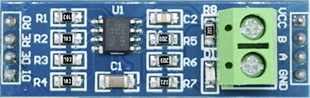
Pin Configuration and Descriptions

Pin Number Name Description
1 RO Receiver Output. This pin outputs the data received via RS485.
2 RE Receiver Enable. A low level on this pin enables the receiver.
3 DE Driver Enable. A high level on this pin enables the driver.
4 DI Driver Input. This pin inputs the data to be sent over RS485.
5 VCC Positive Supply Voltage. Typically +5V.
6 GND Ground. Reference voltage for the power supply.
7 A Non-inverting Receiver/Driver input/output.
8 B Inverting Receiver/Driver input/output.

Usage Instructions

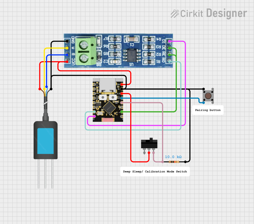
How to Use the RS485 in a Circuit

  1. Power Supply: Connect the VCC pin to a +5V power supply and the GND pin to the ground.
  2. Connecting to a Microcontroller: Interface the DI pin to the TX (transmit) pin of your microcontroller and the RO pin to the RX (receive) pin.
  3. Enabling Communication: Use the RE and DE pins to control the mode of operation. Set both RE and DE low to enable the receiver, and set DE high (and RE low) to enable the transmitter.
  4. Termination Resistors: To prevent signal reflections, a termination resistor (typically 120 ohms) should be placed across the A and B lines at both ends of the bus.

Important Considerations and Best Practices

  • Bus Topology: Use a linear bus topology with termination resistors at each end.
  • Cable Type: Use twisted-pair cables to reduce electromagnetic interference.
  • Grounding: Ensure proper grounding to avoid potential differences between nodes.
  • Biasing Resistors: Sometimes biasing resistors are necessary to ensure a known state when the bus is idle.

Troubleshooting and FAQs

Common Issues

  • Data Corruption: This can be caused by improper termination, excessive noise, or ground potential differences.
  • No Communication: Check if the termination resistors are in place and if the RE and DE pins are being controlled correctly.

Solutions and Tips

  • Signal Integrity: Verify the integrity of the signal with an oscilloscope.
  • Cable Check: Ensure that the cables are not damaged and are properly connected to the A and B terminals.
  • Power Supply: Confirm that the power supply is stable and within the specified voltage range.

FAQs

Q: Can I connect more than 32 devices on an RS485 bus? A: Yes, but you will need to use repeaters to extend the number of allowable nodes.

Q: How can I increase the maximum distance for RS485 communication? A: Lowering the baud rate can increase the maximum cable length.

Q: What is the difference between RS485 and RS232? A: RS485 supports multi-point connections and longer distances at higher speeds compared to RS232, which is for point-to-point communication.

Example Code for Arduino UNO

#include <SoftwareSerial.h>

// RS485 control pins
const int RE_PIN = 2; // Receiver Enable
const int DE_PIN = 3; // Driver Enable

// Initialize software serial port
SoftwareSerial rs485Serial(10, 11); // RX, TX

void setup() {
  pinMode(RE_PIN, OUTPUT);
  pinMode(DE_PIN, OUTPUT);
  
  // Start serial communication
  rs485Serial.begin(9600);
  Serial.begin(9600);
  
  // Set RS485 module to receive mode
  digitalWrite(RE_PIN, LOW);
  digitalWrite(DE_PIN, LOW);
}

void loop() {
  // Check if data is available to read
  if (rs485Serial.available()) {
    int incomingByte = rs485Serial.read();
    Serial.print("Received: ");
    Serial.println(incomingByte, DEC);
  }

  // Check if data is available to send from the serial monitor
  if (Serial.available()) {
    // Set RS485 module to transmit mode
    digitalWrite(RE_PIN, LOW);
    digitalWrite(DE_PIN, HIGH);
    
    char outgoingByte = Serial.read();
    rs485Serial.write(outgoingByte);
    
    // Return to receive mode after sending
    digitalWrite(RE_PIN, LOW);
    digitalWrite(DE_PIN, LOW);
  }
}

This example demonstrates basic RS485 communication with an Arduino UNO. The SoftwareSerial library is used to create a serial port on pins 10 and 11. The RE and DE pins are controlled to switch between receiving and transmitting modes. Data received from the RS485 bus is printed to the Serial Monitor, and data entered into the Serial Monitor is sent onto the RS485 bus.