How to Use SECONDARY & PRIMARY: Examples, Pinouts, and Specs
Introduction
The transformer is a fundamental component in electrical engineering, serving as a device that transfers electrical energy between two or more circuits through electromagnetic induction. Transformers are widely used in power distribution systems, audio systems, and various electronic devices to step-up or step-down voltage levels according to the needs of the application.
Common Applications and Use Cases
- Power Distribution: Transformers are essential for the transmission and distribution of electrical power. They step-up the voltage for efficient long-distance transmission and step-down the voltage for safe local distribution.
- Audio Equipment: In audio systems, transformers are used to match impedances between different components, such as amplifiers and speakers.
- Isolation: Transformers provide galvanic isolation between circuits, which is crucial for safety and noise reduction.
- Voltage Conversion: Electronic devices often use transformers to convert the mains voltage to a lower level suitable for the internal circuitry.
Technical Specifications
Key Technical Details
- Voltage Rating: The maximum input (primary) and output (secondary) voltages the transformer can handle.
- Current Rating: The maximum current the transformer windings can carry without overheating.
- Power Rating: The total amount of power the transformer can transfer from primary to secondary.
- Frequency Range: The operational frequency range over which the transformer can function efficiently.
- Isolation Voltage: The maximum voltage that can be applied between primary and secondary without breakdown.
Pin Configuration and Descriptions
| Pin Number | Description | Notes |
|---|---|---|
| P1 | Primary Winding Start | Connect to AC voltage source |
| P2 | Primary Winding End | Returns to AC voltage source |
| S1 | Secondary Winding Start | Output AC voltage start |
| S2 | Secondary Winding End | Output AC voltage return |
Usage Instructions
How to Use the Transformer in a Circuit
- Identify Transformer Ratings: Ensure the transformer's voltage and current ratings match your application requirements.
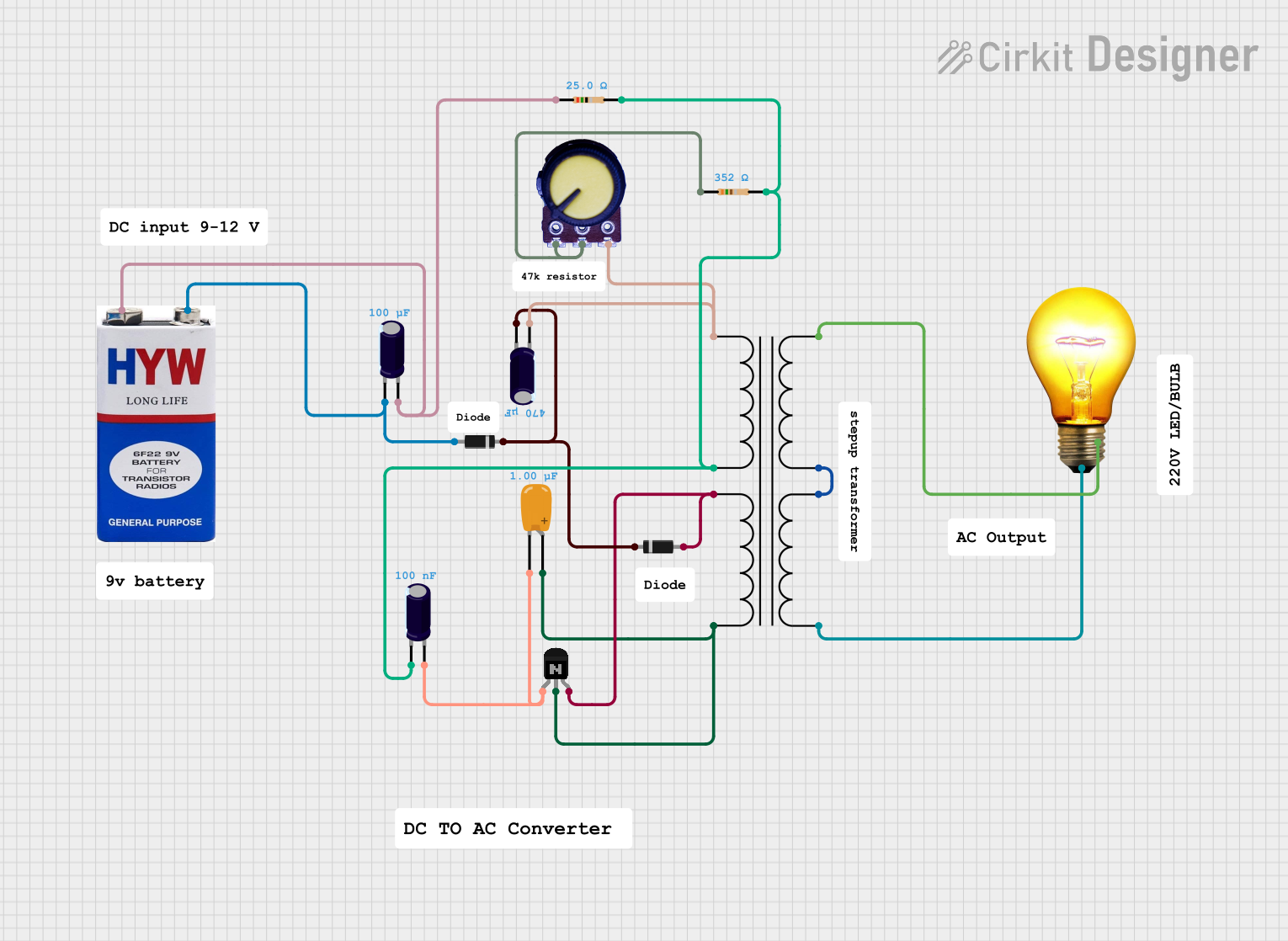
- Circuit Integration: Connect the primary winding (P1 and P2) to the AC voltage source. The secondary winding (S1 and S2) will provide the transformed voltage.
- Load Connection: Connect the load to the secondary winding, ensuring that the load does not exceed the transformer's power rating.
- Safety Precautions: Always fuse the primary side to protect against overcurrent conditions.
Important Considerations and Best Practices
- Thermal Management: Ensure adequate cooling for the transformer to prevent overheating.
- Electromagnetic Interference (EMI): Place the transformer away from sensitive components to minimize EMI.
- Correct Orientation: Follow the manufacturer's datasheet for proper pin orientation and winding connections.
Troubleshooting and FAQs
Common Issues Users Might Face
- Overheating: Caused by exceeding the current or power ratings. Check the load and ensure proper ventilation.
- Humming Noise: This can be due to mechanical vibrations. Ensure the transformer is securely mounted.
- No Output Voltage: Check for proper connections and ensure the input voltage is present and within specifications.
Solutions and Tips for Troubleshooting
- Check Connections: Verify all connections are secure and correct according to the transformer's datasheet.
- Measure Input Voltage: Use a multimeter to confirm the presence and level of the input voltage.
- Inspect for Damage: Look for signs of physical damage or burn marks that could indicate a fault.
Example Code for Arduino UNO
If you're using the transformer to power an Arduino UNO, ensure that the secondary voltage is appropriate for the board (typically 7-12V for the DC input jack). Below is an example code snippet for reading an analog voltage with an Arduino UNO:
// Define the analog input pin
int analogInputPin = A0;

void setup() {
  // Initialize serial communication at 9600 bits per second:
  Serial.begin(9600);
}

void loop() {
  // Read the input on analog pin 0:
  int sensorValue = analogRead(analogInputPin);
  // Convert the analog reading to voltage (assuming 5V for the Arduino board):
  float voltage = sensorValue * (5.0 / 1023.0);
  // Print out the voltage
  Serial.println(voltage);
  // Delay for a bit to get stable readings
  delay(1000);
}
Remember, the above code assumes that the transformer's secondary voltage has been rectified and regulated to be compatible with the Arduino's operating voltage. Always use a voltage regulator to ensure the voltage is within safe limits for your microcontroller.
Explore Projects Built with SECONDARY & PRIMARY

Explore Projects Built with SECONDARY & PRIMARY