
How to Use YCC-2S: Examples, Pinouts, and Specs
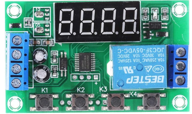
 Design with YCC-2S in Cirkit Designer
Introduction
The YCC-2S is a compact, dual-channel current sensor designed for precise measurement of electrical currents in various applications. It features high accuracy, a wide operating range, and a robust design, making it suitable for both industrial and consumer electronics. The YCC-2S is commonly used in power monitoring systems, battery management systems, motor control circuits, and energy-efficient devices.
Explore Projects Built with YCC-2S
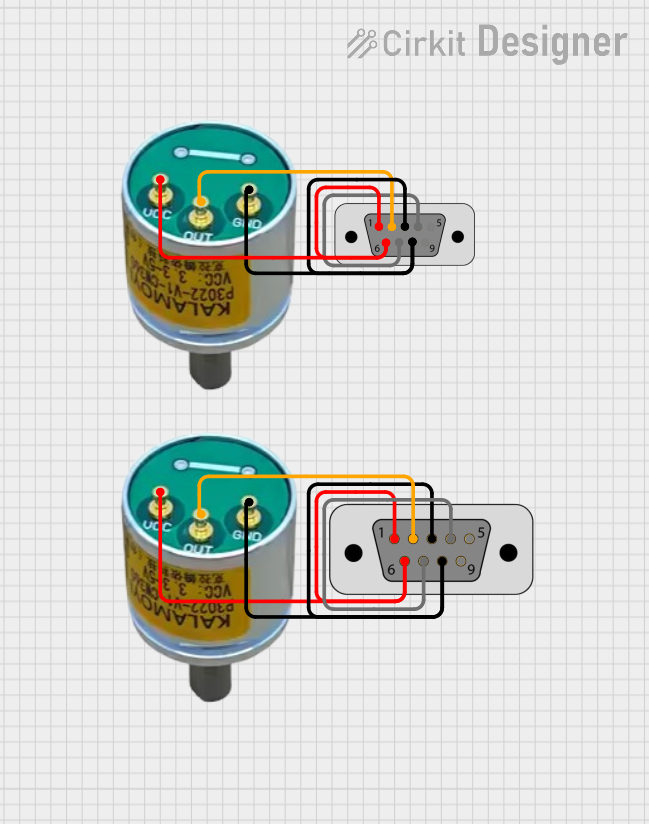 Open Project in Cirkit Designer
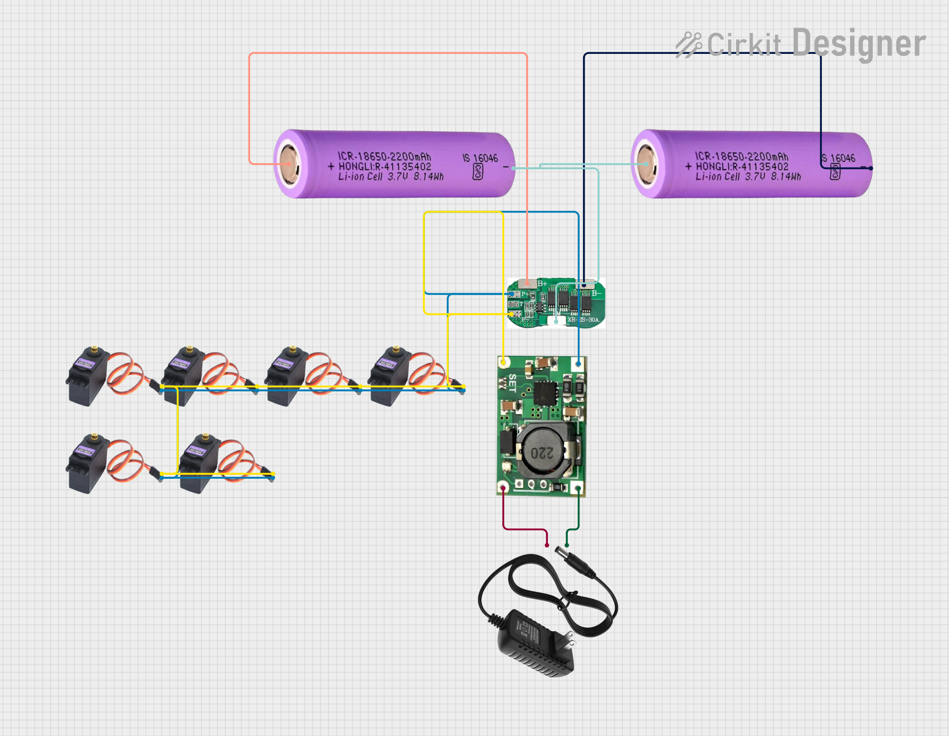 Open Project in Cirkit Designer
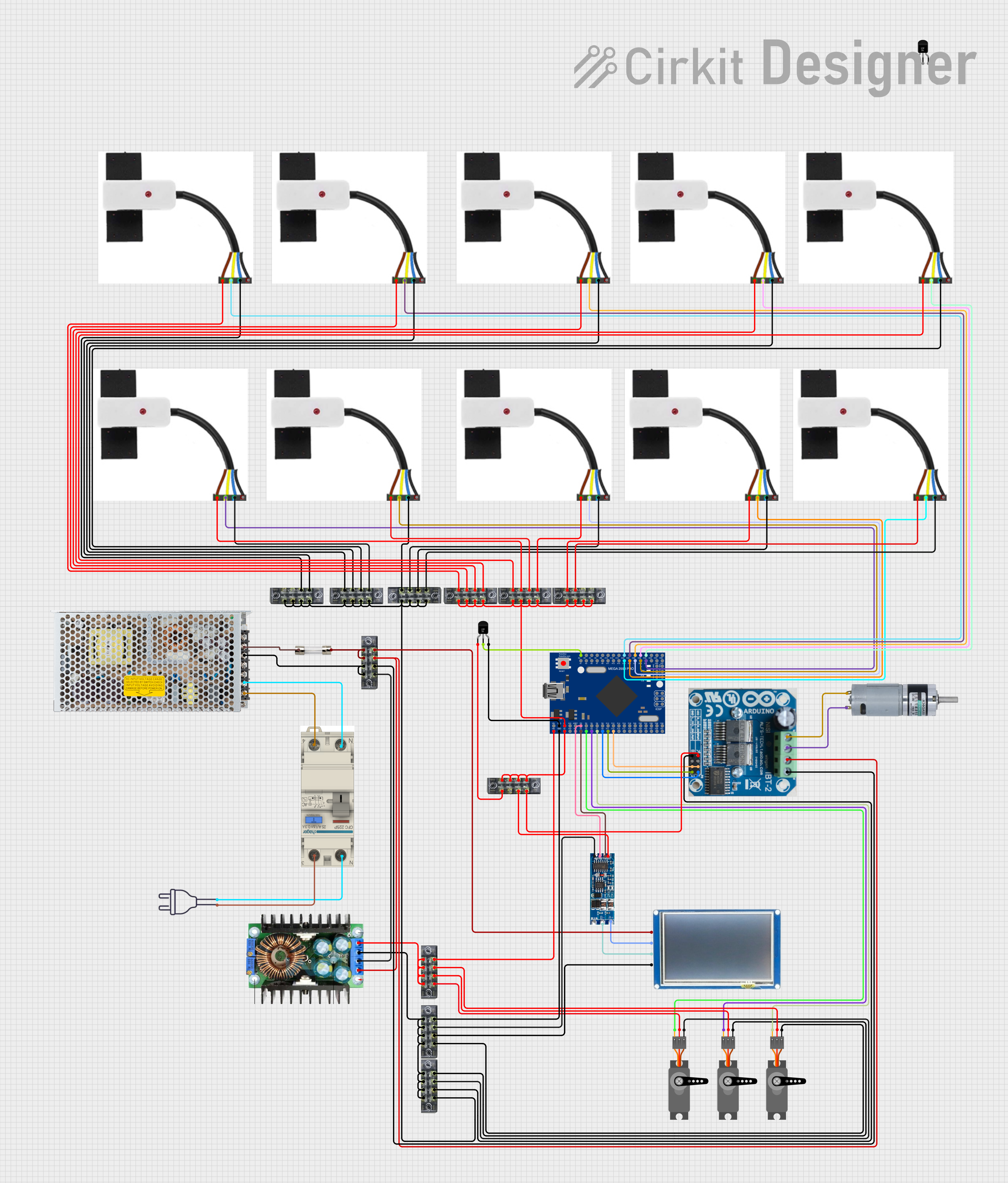 Open Project in Cirkit Designer
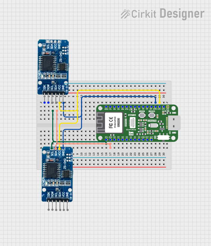 Open Project in Cirkit Designer
Explore Projects Built with YCC-2S
Open Project in Cirkit DesignerOpen Project in Cirkit DesignerOpen Project in Cirkit DesignerOpen Project in Cirkit DesignerTechnical Specifications
The YCC-2S offers reliable performance with the following key specifications:
| Parameter | Value |
|---|---|
| Operating Voltage | 3.3V to 5V |
| Current Measurement Range | ±30A per channel |
| Accuracy | ±1% |
| Channels | 2 |
| Output Type | Analog Voltage |
| Bandwidth | 50 kHz |
| Operating Temperature | -40°C to +85°C |
| Dimensions | 25mm x 15mm x 5mm |
Pin Configuration and Descriptions
The YCC-2S has a total of 6 pins, as described in the table below:
| Pin | Name | Description |
|---|---|---|
| 1 | VCC | Power supply input (3.3V to 5V) |
| 2 | GND | Ground connection |
| 3 | OUT1 | Analog output for Channel 1 current measurement |
| 4 | OUT2 | Analog output for Channel 2 current measurement |
| 5 | IN+ | Positive input for current sensing (shared for both channels) |
| 6 | IN- | Negative input for current sensing (shared for both channels) |
Usage Instructions
How to Use the YCC-2S in a Circuit
- Power Supply: Connect the VCC pin to a 3.3V or 5V power source and the GND pin to the ground of your circuit.
- Current Sensing: Pass the current-carrying conductor through the sensor's input terminals (IN+ and IN-). Ensure proper polarity for accurate measurements.
- Output Connections: Connect OUT1 and OUT2 to the analog input pins of a microcontroller or data acquisition system to read the current measurements for Channel 1 and Channel 2, respectively.
- Signal Processing: Use the analog voltage outputs to calculate the current using the sensor's sensitivity (provided in the datasheet).
Important Considerations and Best Practices
- Calibration: For optimal accuracy, calibrate the sensor in your specific application environment.
- Noise Reduction: Use decoupling capacitors (e.g., 0.1µF) between VCC and GND to minimize noise.
- Current Range: Ensure the current being measured does not exceed the ±30A range to avoid damage or inaccurate readings.
- Temperature Effects: Operate the sensor within the specified temperature range to maintain accuracy.
Example: Connecting YCC-2S to an Arduino UNO
Below is an example of how to connect and read data from the YCC-2S using an Arduino UNO:
Circuit Connections
- Connect the VCC pin of the YCC-2S to the 5V pin on the Arduino.
- Connect the GND pin of the YCC-2S to the GND pin on the Arduino.
- Connect OUT1 to the A0 pin on the Arduino for Channel 1.
- Connect OUT2 to the A1 pin on the Arduino for Channel 2.
Arduino Code
// Define the analog input pins for the YCC-2S outputs
const int channel1Pin = A0; // Channel 1 output connected to A0
const int channel2Pin = A1; // Channel 2 output connected to A1

void setup() {
  Serial.begin(9600); // Initialize serial communication at 9600 baud
}

void loop() {
  // Read the analog values from the YCC-2S outputs
  int channel1Value = analogRead(channel1Pin);
  int channel2Value = analogRead(channel2Pin);

  // Convert the analog values to current (example calculation)
  // Assuming a sensitivity of 66mV/A and a 5V reference voltage
  float current1 = (channel1Value * 5.0 / 1023.0) / 0.066;
  float current2 = (channel2Value * 5.0 / 1023.0) / 0.066;

  // Print the current values to the Serial Monitor
  Serial.print("Channel 1 Current: ");
  Serial.print(current1);
  Serial.println(" A");

  Serial.print("Channel 2 Current: ");
  Serial.print(current2);
  Serial.println(" A");

  delay(1000); // Wait for 1 second before the next reading
}
Troubleshooting and FAQs
Common Issues
No Output Signal:
- Cause: Incorrect power supply or loose connections.
- Solution: Verify that the VCC and GND pins are properly connected and the supply voltage is within the specified range.
Inaccurate Readings:
- Cause: Calibration not performed or excessive noise in the circuit.
- Solution: Calibrate the sensor and add decoupling capacitors to reduce noise.
Output Voltage Saturation:
- Cause: Current exceeds the ±30A range.
- Solution: Ensure the current being measured is within the sensor's range.
FAQs
Q: Can the YCC-2S measure both AC and DC currents?
A: Yes, the YCC-2S can measure both AC and DC currents within its specified range.
Q: What is the sensitivity of the YCC-2S?
A: The sensitivity is typically 66mV/A, but refer to the datasheet for precise values.
Q: Can I use the YCC-2S with a 3.3V microcontroller?
A: Yes, the YCC-2S operates with a supply voltage of 3.3V to 5V, making it compatible with 3.3V systems.
Q: How do I protect the sensor from overcurrent?
A: Use a fuse or current-limiting resistor in your circuit to prevent currents exceeding the sensor's range.