How to Use ESP32-S3 DevKitC-1 WROOM-1: Examples, Pinouts, and Specs
Introduction
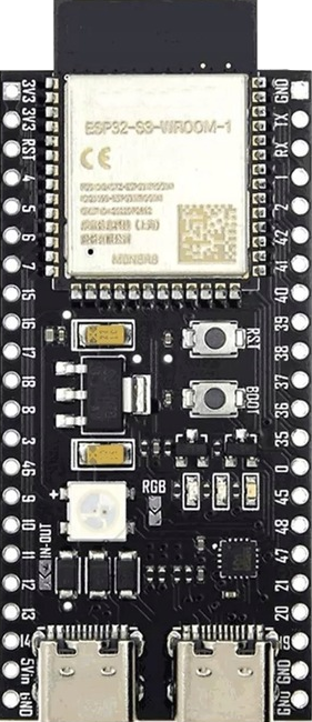
The ESP32-S3 DevKitC-1 WROOM-1 is a development board designed by Espressif Systems. It is based on the ESP32-S3-WROOM-1 module, which features a dual-core Xtensa LX7 processor, integrated Wi-Fi (802.11 b/g/n), and Bluetooth 5.0 LE capabilities. This board is ideal for IoT applications, AI processing, and edge computing due to its powerful processing capabilities and support for AI acceleration.
Explore Projects Built with ESP32-S3 DevKitC-1 WROOM-1

Explore Projects Built with ESP32-S3 DevKitC-1 WROOM-1
Common Applications and Use Cases
- IoT devices and smart home automation
- Wearable electronics
- AI and machine learning at the edge
- Wireless communication and networking
- Industrial automation and control systems
- Prototyping and development of embedded systems
Technical Specifications
The following are the key technical details of the ESP32-S3 DevKitC-1 WROOM-1:
| Specification | Details |
|---|---|
| Processor | Dual-core Xtensa LX7, up to 240 MHz |
| Flash Memory | 4 MB (default) |
| RAM | 512 KB SRAM + 8 MB PSRAM |
| Wireless Connectivity | Wi-Fi 802.11 b/g/n, Bluetooth 5.0 LE |
| Operating Voltage | 3.3V (regulated from USB or external power source) |
| GPIO Pins | 21 GPIO pins, configurable for various functions |
| USB Interface | USB Type-C for power, programming, and debugging |
| AI Acceleration | Vector instructions and hardware support for AI/ML tasks |
| Dimensions | 54 mm x 25.5 mm |
Pin Configuration and Descriptions
The ESP32-S3 DevKitC-1 WROOM-1 features a 2x19 pin header layout. Below is the pinout description:
| Pin Name | Type | Description |
|---|---|---|
| 3V3 | Power | 3.3V power output |
| GND | Power | Ground |
| GPIO0 | Input/Output | General-purpose I/O, boot mode selection |
| GPIO1 | Input/Output | General-purpose I/O, UART TX |
| GPIO2 | Input/Output | General-purpose I/O, ADC, touch sensor |
| GPIO3 | Input/Output | General-purpose I/O, UART RX |
| GPIO4 | Input/Output | General-purpose I/O, ADC, touch sensor |
| GPIO5 | Input/Output | General-purpose I/O, PWM, ADC |
| EN | Input | Reset pin (active low) |
| VIN | Power | Input voltage (5V from USB or external source) |
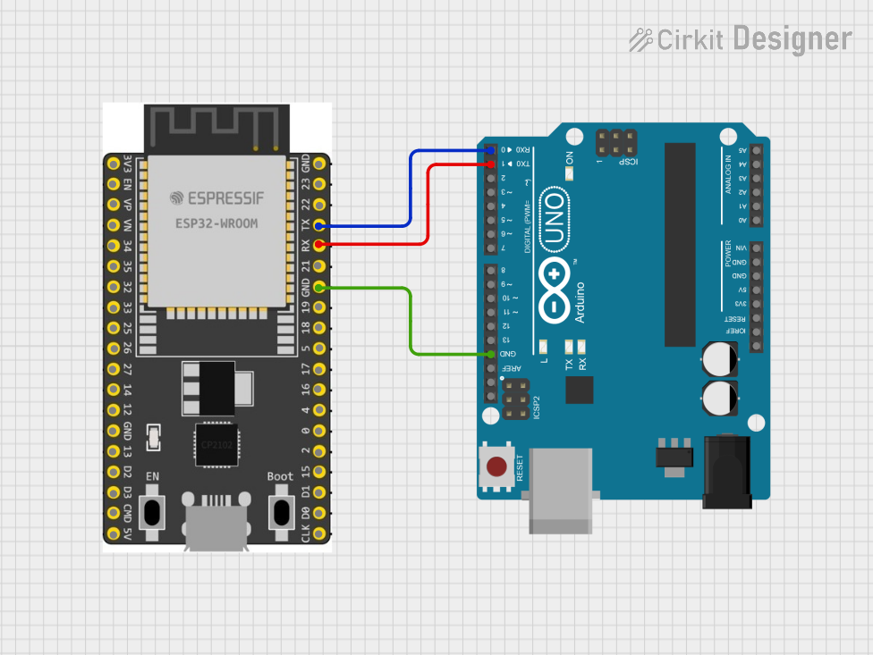
| TXD0 | Output | UART0 transmit |
| RXD0 | Input | UART0 receive |
| IO34-39 | Input | Input-only pins, typically used for ADC or touch sensors |
For a complete pinout diagram, refer to the official Espressif documentation.
Usage Instructions
How to Use the ESP32-S3 DevKitC-1 WROOM-1 in a Circuit
Powering the Board:
- Connect the board to a computer or USB power source using a USB Type-C cable.
- Alternatively, supply 5V to the VIN pin for external power.
Programming the Board:
- Install the Arduino IDE or Espressif's ESP-IDF development framework.
- Add the ESP32-S3 board support package to your IDE.
- Connect the board to your computer and select the appropriate COM port.
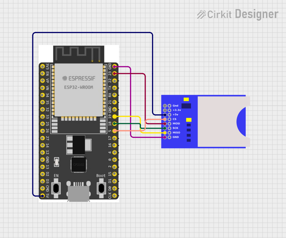
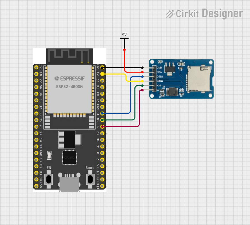
Connecting Peripherals:
- Use the GPIO pins to connect sensors, actuators, or other peripherals.
- Ensure that the voltage levels of connected devices are compatible with the 3.3V logic of the ESP32-S3.
Uploading Code:
- Write your program in the IDE and upload it to the board.
- The board will automatically reset and run the uploaded code.
Important Considerations and Best Practices
- Voltage Levels: Ensure all connected peripherals operate at 3.3V logic levels to avoid damaging the board.
- Boot Mode: To enter bootloader mode, hold the BOOT button while pressing the EN (reset) button.
- Power Supply: Use a stable power source to avoid unexpected resets or malfunctions.
- Wi-Fi and Bluetooth: Avoid placing the board in metal enclosures that may interfere with wireless signals.
Example Code for Arduino IDE
Below is an example of how to blink an LED connected to GPIO2:
// Define the GPIO pin for the LED
#define LED_PIN 2

void setup() {
  // Set the LED pin as an output
  pinMode(LED_PIN, OUTPUT);
}

void loop() {
  // Turn the LED on
  digitalWrite(LED_PIN, HIGH);
  delay(1000); // Wait for 1 second

  // Turn the LED off
  digitalWrite(LED_PIN, LOW);
  delay(1000); // Wait for 1 second
}
Troubleshooting and FAQs
Common Issues and Solutions
The board is not detected by the computer:
- Ensure the USB cable is functional and supports data transfer.
- Check if the correct drivers for the ESP32-S3 are installed on your computer.
Code upload fails:
- Verify that the correct COM port is selected in the IDE.
- Hold the BOOT button while pressing the EN button to enter bootloader mode.
Wi-Fi connection issues:
- Ensure the Wi-Fi credentials in your code are correct.
- Check for interference or weak signal strength in your environment.
Board resets unexpectedly:
- Use a stable power source with sufficient current (at least 500 mA).
- Avoid short circuits or overloading the GPIO pins.
FAQs
Q: Can I use 5V peripherals with the ESP32-S3?
A: No, the GPIO pins operate at 3.3V logic levels. Use a level shifter for 5V peripherals.Q: How do I enable Bluetooth functionality?
A: Use the ESP-IDF or Arduino IDE libraries to initialize and configure Bluetooth.Q: What is the maximum current draw of the board?
A: The board typically draws around 240 mA during peak operation with Wi-Fi and Bluetooth enabled.
For further assistance, refer to the official Espressif documentation or community forums.