How to Use Drv8833: Examples, Pinouts, and Specs
Introduction
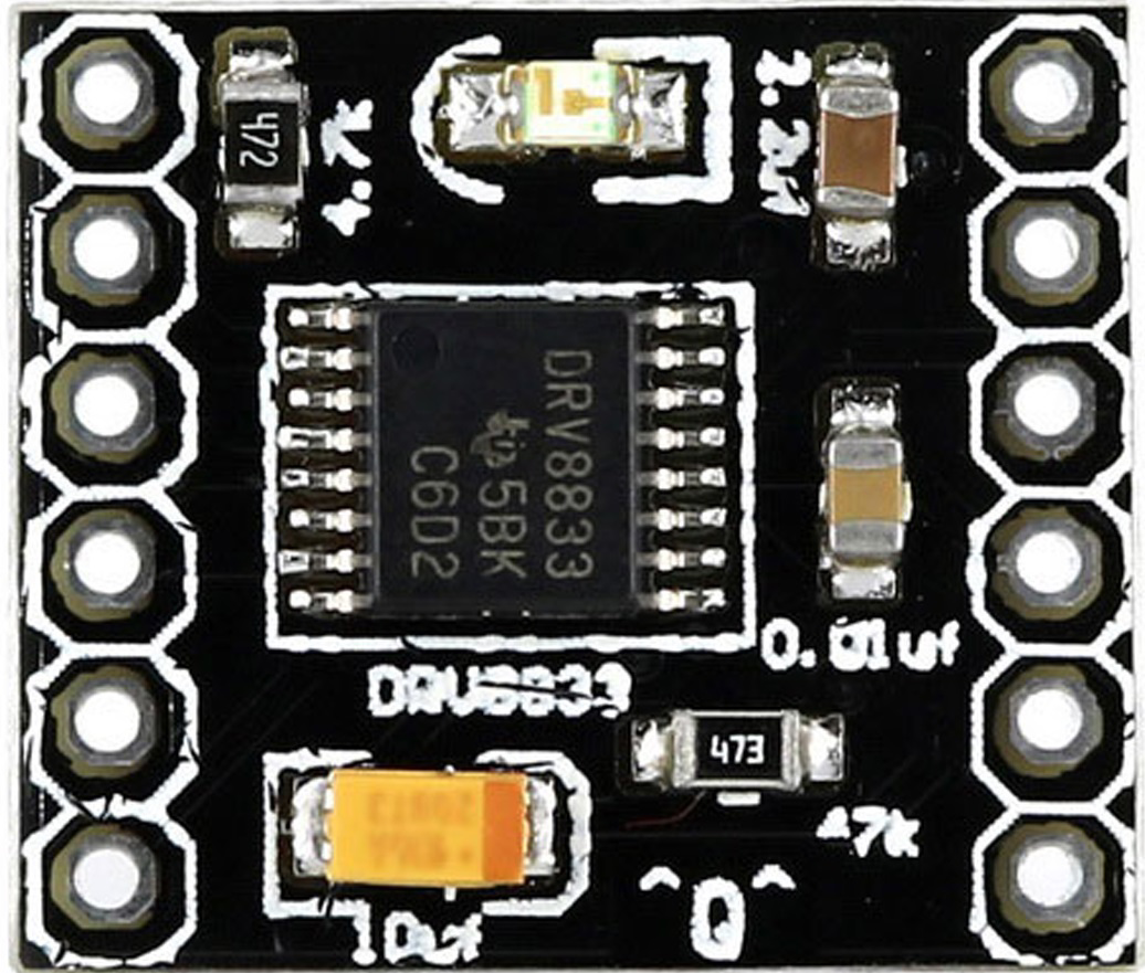
The DRV8833 is a dual H-bridge motor driver designed to control two DC motors or a single stepper motor. It operates within a voltage range of 2.7V to 10.8V and can deliver up to 1.5A of continuous current per channel. This compact and efficient motor driver is equipped with built-in protection features, including overcurrent protection and thermal shutdown, ensuring reliable operation in demanding environments.
Explore Projects Built with Drv8833

Explore Projects Built with Drv8833
Common Applications and Use Cases
- Robotics and automation systems
- Remote-controlled vehicles
- Conveyor belts and small industrial machines
- DIY electronics projects
- Stepper motor control for 3D printers and CNC machines
Technical Specifications
Key Technical Details
| Parameter | Value |
|---|---|
| Motor Driver Type | Dual H-Bridge |
| Operating Voltage Range | 2.7V to 10.8V |
| Continuous Current (per channel) | 1.5A |
| Peak Current (per channel) | 2A |
| Logic Voltage Range | 1.8V to 7V |
| PWM Frequency | Up to 250 kHz |
| Built-in Protections | Overcurrent, Thermal Shutdown |
| Package Type | HTSSOP-16 |
Pin Configuration and Descriptions
The DRV8833 comes in a 16-pin HTSSOP package. Below is the pinout and description:
| Pin Number | Pin Name | Description |
|---|---|---|
| 1 | AIN1 | Input 1 for H-Bridge A (controls motor direction) |
| 2 | AIN2 | Input 2 for H-Bridge A (controls motor direction) |
| 3 | AVREF | Reference voltage for H-Bridge A (sets motor speed via PWM) |
| 4 | AGND | Ground for H-Bridge A |
| 5 | AO1 | Output 1 for H-Bridge A (connect to motor terminal) |
| 6 | AO2 | Output 2 for H-Bridge A (connect to motor terminal) |
| 7 | VM | Motor power supply (2.7V to 10.8V) |
| 8 | PGND | Power ground |
| 9 | BO2 | Output 2 for H-Bridge B (connect to motor terminal) |
| 10 | BO1 | Output 1 for H-Bridge B (connect to motor terminal) |
| 11 | BGND | Ground for H-Bridge B |
| 12 | BVREF | Reference voltage for H-Bridge B (sets motor speed via PWM) |
| 13 | BIN2 | Input 2 for H-Bridge B (controls motor direction) |
| 14 | BIN1 | Input 1 for H-Bridge B (controls motor direction) |
| 15 | nSLEEP | Sleep mode control (active low, pull high to enable the driver) |
| 16 | nFAULT | Fault output (active low, indicates fault conditions like overcurrent) |
Usage Instructions
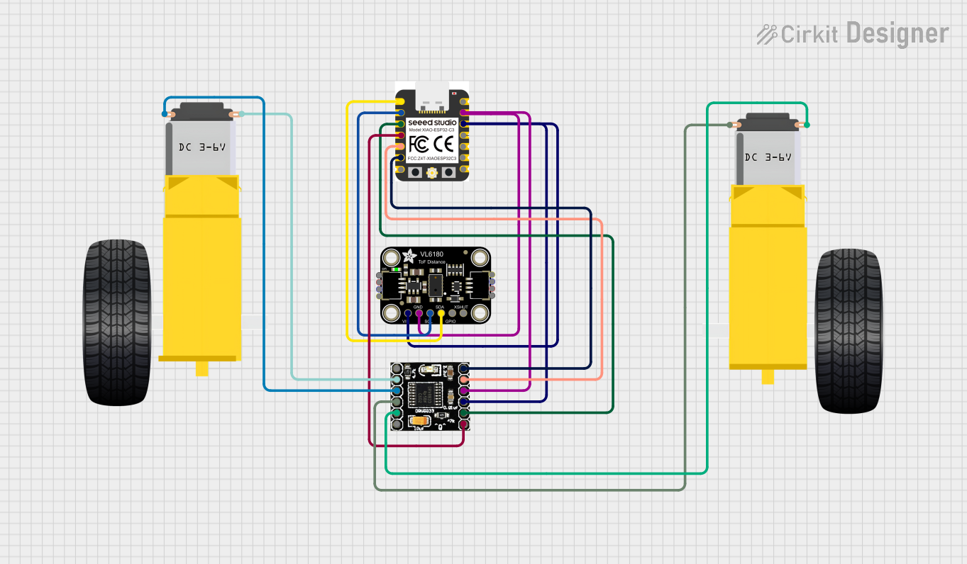
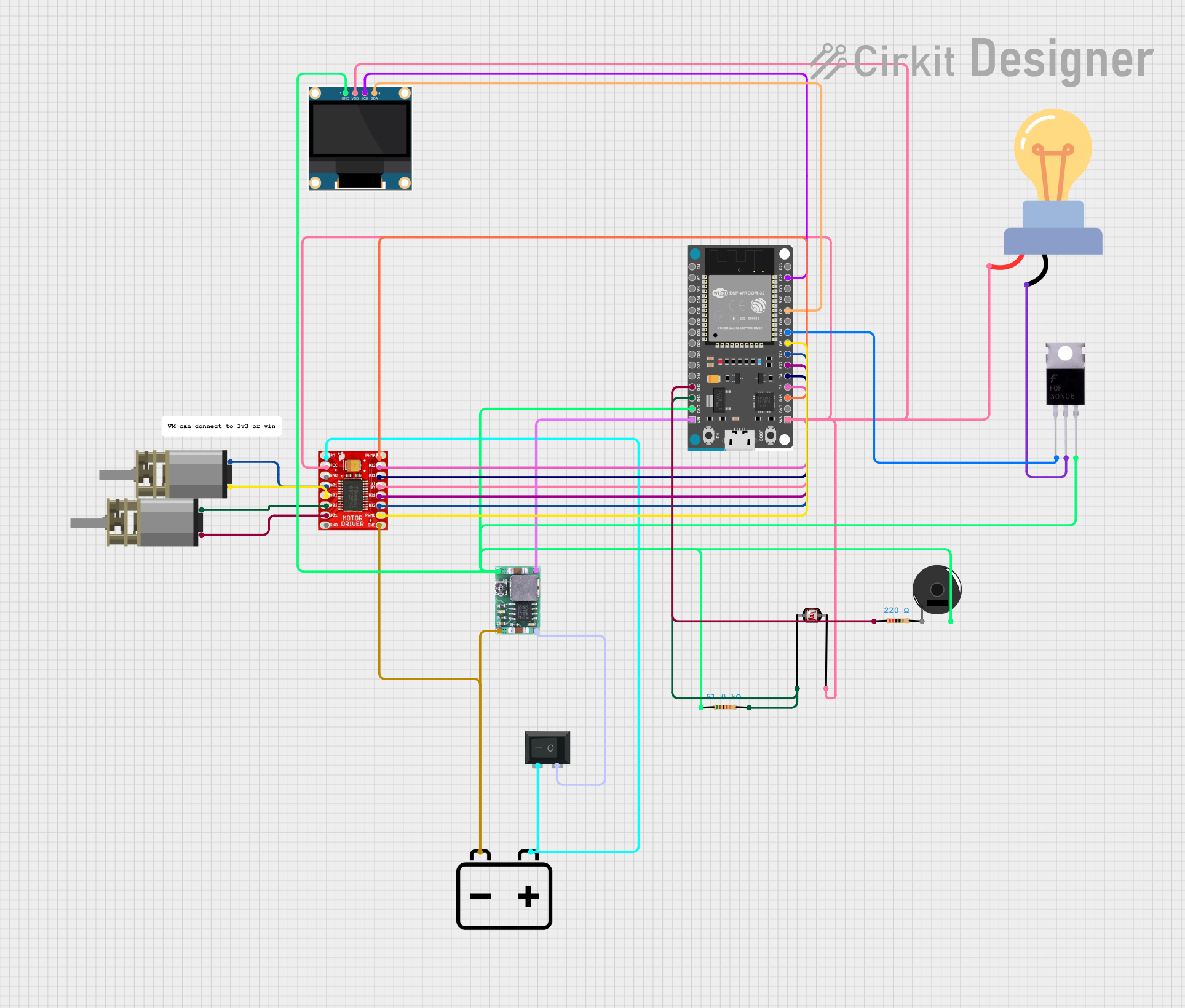
How to Use the DRV8833 in a Circuit
- Power Supply: Connect the motor power supply (VM) to the VM pin. Ensure the voltage is within the range of 2.7V to 10.8V. Connect the ground of the power supply to PGND.
- Logic Inputs: Use the AIN1, AIN2, BIN1, and BIN2 pins to control the direction of the motors. These pins accept logic levels between 1.8V and 7V.
- Motor Connections: Connect the motor terminals to AO1/AO2 for Motor A and BO1/BO2 for Motor B.
- PWM Control: Apply a PWM signal to the AVREF and BVREF pins to control motor speed.
- Sleep Mode: Pull the nSLEEP pin high to enable the driver. Pull it low to put the driver into low-power sleep mode.
- Fault Monitoring: Monitor the nFAULT pin for fault conditions. If the pin is pulled low, check for overcurrent or thermal shutdown.
Important Considerations and Best Practices
- Use decoupling capacitors (e.g., 0.1µF and 10µF) close to the VM pin to stabilize the power supply.
- Avoid exceeding the maximum current rating of 1.5A per channel to prevent damage.
- Ensure proper heat dissipation, especially when driving motors at high currents.
- Use pull-up resistors on the nSLEEP and nFAULT pins if required by your circuit design.
Example: Using DRV8833 with Arduino UNO
Below is an example of controlling a DC motor using the DRV8833 and Arduino UNO:
// Define motor control pins
const int AIN1 = 9;  // Connect to DRV8833 AIN1 pin
const int AIN2 = 10; // Connect to DRV8833 AIN2 pin
const int PWMA = 3;  // Connect to DRV8833 AVREF pin (PWM control)

void setup() {
  // Set motor control pins as outputs
  pinMode(AIN1, OUTPUT);
  pinMode(AIN2, OUTPUT);
  pinMode(PWMA, OUTPUT);
}

void loop() {
  // Rotate motor forward
  digitalWrite(AIN1, HIGH); // Set AIN1 high
  digitalWrite(AIN2, LOW);  // Set AIN2 low
  analogWrite(PWMA, 128);   // Set motor speed (0-255)

  delay(2000); // Run motor for 2 seconds

  // Rotate motor backward
  digitalWrite(AIN1, LOW);  // Set AIN1 low
  digitalWrite(AIN2, HIGH); // Set AIN2 high
  analogWrite(PWMA, 128);   // Set motor speed (0-255)

  delay(2000); // Run motor for 2 seconds

  // Stop motor
  digitalWrite(AIN1, LOW);  // Set AIN1 low
  digitalWrite(AIN2, LOW);  // Set AIN2 low
  analogWrite(PWMA, 0);     // Set motor speed to 0

  delay(2000); // Wait for 2 seconds before repeating
}
Troubleshooting and FAQs
Common Issues and Solutions
Motor Not Spinning:
- Ensure the nSLEEP pin is pulled high to enable the driver.
- Verify that the motor power supply (VM) is connected and within the specified voltage range.
- Check the logic input pins (AIN1, AIN2, BIN1, BIN2) for proper signals.
Overheating:
- Ensure the current drawn by the motor does not exceed 1.5A per channel.
- Improve heat dissipation by using a heatsink or ensuring proper ventilation.
nFAULT Pin Pulled Low:
- Check for overcurrent or thermal shutdown conditions.
- Reduce the motor load or allow the driver to cool down before restarting.
PWM Control Not Working:
- Verify that the PWM signal is connected to the AVREF or BVREF pins.
- Ensure the PWM frequency is within the supported range (up to 250 kHz).
FAQs
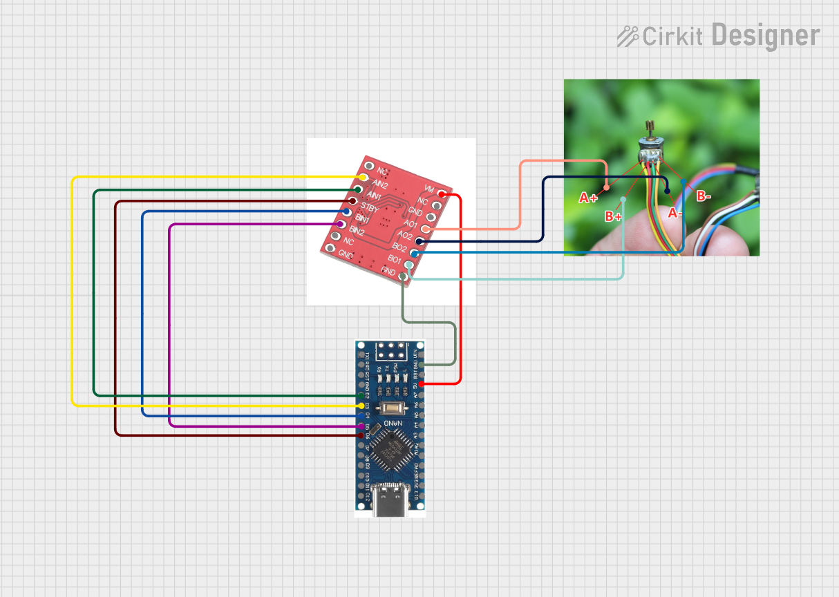
Q: Can the DRV8833 drive a stepper motor?
A: Yes, the DRV8833 can drive a single bipolar stepper motor by using both H-bridges. You will need to sequence the inputs (AIN1, AIN2, BIN1, BIN2) appropriately to control the stepper motor.
Q: What happens if the motor draws more than 1.5A?
A: The DRV8833 has built-in overcurrent protection. If the current exceeds the limit, the driver will shut down to protect itself. Reduce the motor load or use a motor with lower current requirements.
Q: Can I use the DRV8833 with a 3.3V microcontroller?
A: Yes, the DRV8833 supports logic levels as low as 1.8V, making it compatible with 3.3V microcontrollers.