
How to Use Adafruit Metro Mini: Examples, Pinouts, and Specs
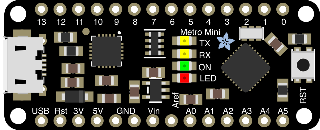
 Design with Adafruit Metro Mini in Cirkit Designer
Introduction
The Adafruit Metro Mini (Manufacturer Part ID: 2590) is a compact microcontroller board based on the ATmega328P, designed for easy integration into a wide range of electronic projects. It offers USB connectivity for programming and power, making it a versatile and user-friendly choice for both beginners and experienced developers. The Metro Mini is fully compatible with the Arduino IDE, allowing seamless development and deployment of projects.
Explore Projects Built with Adafruit Metro Mini
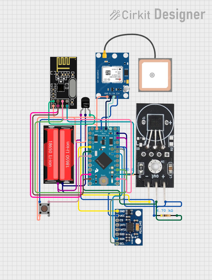 Open Project in Cirkit Designer
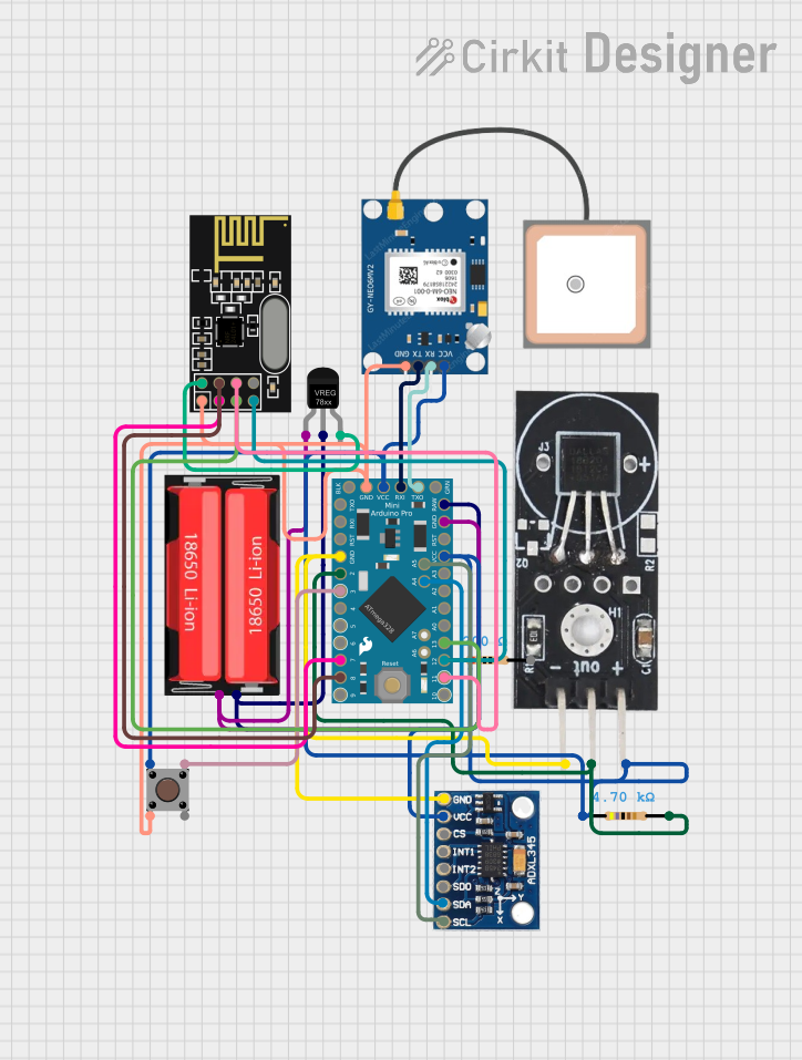 Open Project in Cirkit Designer
 Open Project in Cirkit Designer
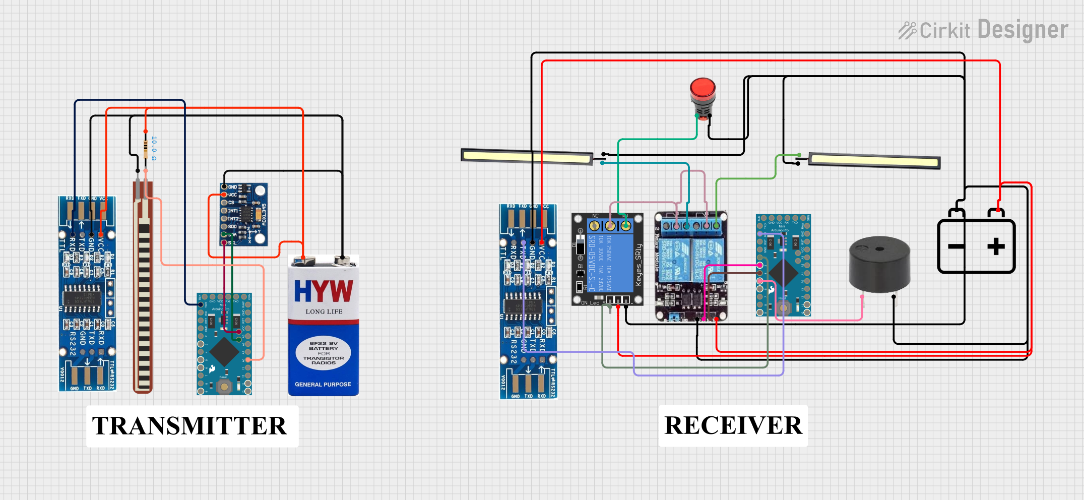 Open Project in Cirkit Designer
Explore Projects Built with Adafruit Metro Mini
Open Project in Cirkit DesignerOpen Project in Cirkit DesignerOpen Project in Cirkit DesignerOpen Project in Cirkit DesignerCommon Applications and Use Cases
- Prototyping and development of embedded systems
- Robotics and automation projects
- IoT (Internet of Things) devices
- Wearable electronics
- Educational tools for learning microcontroller programming
Technical Specifications
The Adafruit Metro Mini is packed with features that make it a powerful yet compact microcontroller board. Below are its key technical specifications:
Key Technical Details
- Microcontroller: ATmega328P
- Operating Voltage: 5V
- Input Voltage (recommended): 7-9V via VIN pin
- Input Voltage (limit): 6-20V
- Digital I/O Pins: 14 (6 of which provide PWM output)
- Analog Input Pins: 6
- Flash Memory: 32 KB (0.5 KB used by bootloader)
- SRAM: 2 KB
- EEPROM: 1 KB
- Clock Speed: 16 MHz
- USB Interface: Micro-USB for programming and power
- Dimensions: 48mm x 18mm x 2mm
- Weight: 5g
Pin Configuration and Descriptions
The Metro Mini features a total of 20 pins, including digital, analog, power, and communication pins. Below is a detailed description of the pin configuration:
Digital Pins
| Pin Number | Function | Description |
|---|---|---|
| D0 - D1 | UART (RX, TX) | Serial communication pins |
| D2 - D13 | Digital I/O | General-purpose digital input/output pins |
| D3, D5, D6, D9, D10, D11 | PWM Output | Pulse Width Modulation capable pins |
Analog Pins
| Pin Number | Function | Description |
|---|---|---|
| A0 - A5 | Analog Input | Analog-to-digital conversion (10-bit) |
Power Pins
| Pin Name | Function | Description |
|---|---|---|
| VIN | Input Voltage | External power input (7-9V recommended) |
| 5V | Regulated 5V Output | Provides 5V output for external components |
| 3.3V | Regulated 3.3V Output | Provides 3.3V output for external components |
| GND | Ground | Common ground for the circuit |
| RESET | Reset | Resets the microcontroller |
Communication Pins
| Pin Name | Function | Description |
|---|---|---|
| SDA | I2C Data | Data line for I2C communication |
| SCL | I2C Clock | Clock line for I2C communication |
| MOSI | SPI Master Out Slave In | SPI data output from master |
| MISO | SPI Master In Slave Out | SPI data input to master |
| SCK | SPI Clock | Clock line for SPI communication |
Usage Instructions
The Adafruit Metro Mini is designed for ease of use, especially for those familiar with Arduino boards. Below are the steps and best practices for using the Metro Mini in your projects.
How to Use the Metro Mini in a Circuit
Powering the Board:
- Connect the Metro Mini to your computer via a Micro-USB cable for programming and power.
- Alternatively, supply external power (7-9V recommended) to the VIN pin.
Programming the Board:
- Install the Arduino IDE on your computer.
- Select "Arduino/Genuino Uno" as the board type in the Arduino IDE.
- Choose the correct COM port for the Metro Mini.
- Write or load your Arduino sketch and upload it to the board.
Connecting Components:
- Use the digital and analog pins to connect sensors, actuators, and other peripherals.
- Ensure proper voltage levels for connected components to avoid damage.
Using Communication Protocols:
- Use the UART pins (D0, D1) for serial communication.
- Use the I2C pins (SDA, SCL) for connecting I2C devices.
- Use the SPI pins (MOSI, MISO, SCK) for SPI communication.
Important Considerations and Best Practices
- Avoid exceeding the voltage limits of the VIN pin (6-20V) to prevent damage.
- Use appropriate resistors or level shifters when interfacing with 3.3V devices.
- Ensure proper grounding for all connected components to avoid noise or erratic behavior.
- Use the RESET pin to manually reset the board if needed.
Example Code for Arduino UNO-Compatible Projects
Below is an example code snippet to blink an LED connected to pin D13:
// Blink an LED connected to pin D13
// This example demonstrates basic digital output functionality

void setup() {
  pinMode(13, OUTPUT); // Set pin D13 as an output
}

void loop() {
  digitalWrite(13, HIGH); // Turn the LED on
  delay(1000);            // Wait for 1 second
  digitalWrite(13, LOW);  // Turn the LED off
  delay(1000);            // Wait for 1 second
}
Troubleshooting and FAQs
Common Issues Users Might Face
Board Not Recognized by Computer:
- Ensure the USB cable is functional and supports data transfer.
- Check if the correct COM port is selected in the Arduino IDE.
- Install the necessary USB drivers for the Metro Mini.
Sketch Fails to Upload:
- Verify that "Arduino/Genuino Uno" is selected as the board type.
- Ensure no other application is using the COM port.
- Press the RESET button on the board before uploading.
Components Not Responding:
- Double-check wiring and connections.
- Ensure components are powered correctly and within voltage limits.
- Use a multimeter to verify continuity and voltage levels.
Solutions and Tips for Troubleshooting
- Reset the Board: Press the RESET button to restart the microcontroller.
- Check Power Supply: Ensure the board is receiving adequate power (via USB or VIN).
- Reinstall Drivers: If the board is not recognized, reinstall the USB drivers.
- Test with Simple Sketches: Upload a basic sketch (e.g., Blink) to verify functionality.
- Inspect Connections: Ensure all connections are secure and correctly oriented.
By following this documentation, you can effectively integrate the Adafruit Metro Mini into your projects and troubleshoot common issues with ease.