How to Use LSM6DSO: Examples, Pinouts, and Specs
Introduction
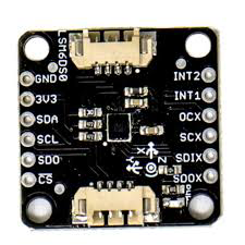
The LSM6DSO is a 6-axis inertial sensor manufactured by Adafruit (Part ID: LSM6DSOTR). It integrates a 3-axis accelerometer and a 3-axis gyroscope into a single compact package, making it ideal for motion tracking and orientation detection. This sensor is widely used in applications such as smartphones, wearables, gaming devices, robotics, and IoT systems. Its digital output interface and low power consumption make it a versatile and efficient choice for high-performance motion sensing.
Explore Projects Built with LSM6DSO


Explore Projects Built with LSM6DSO
Common Applications:
- Motion tracking in smartphones and tablets
- Fitness and health monitoring in wearables
- Gesture recognition in gaming devices
- Orientation detection in robotics and drones
- Vibration monitoring in industrial IoT systems
Technical Specifications
Key Technical Details:
- Supply Voltage: 1.71V to 3.6V
- Current Consumption:
- Accelerometer: 0.55 mA (typical)
- Gyroscope: 0.85 mA (typical)
- Measurement Ranges:
- Accelerometer: ±2g, ±4g, ±8g, ±16g
- Gyroscope: ±125°/s, ±250°/s, ±500°/s, ±1000°/s, ±2000°/s
- Output Data Rate (ODR): Up to 6.66 kHz
- Interface: I²C (up to 1 MHz) and SPI (up to 10 MHz)
- Operating Temperature: -40°C to +85°C
- Package: LGA-14 (2.5 mm x 3 mm x 0.83 mm)
Pin Configuration and Descriptions:
The LSM6DSO has 14 pins, as described in the table below:
| Pin Name | Type | Description |
|---|---|---|
| VDD | Power Supply | Main power supply (1.71V to 3.6V). |
| VDDIO | Power Supply | I/O interface voltage supply. |
| GND | Ground | Ground connection. |
| SCL/SPC | Input | I²C clock line (SCL) or SPI clock line (SPC). |
| SDA/SDI/SDO | Input/Output | I²C data line (SDA), SPI data input (SDI), or SPI data output (SDO). |
| CS | Input | SPI chip select (active low). |
| INT1 | Output | Interrupt 1 signal. Configurable for various events. |
| INT2 | Output | Interrupt 2 signal. Configurable for various events. |
| RES (x6) | Reserved | Reserved pins. Must be left unconnected or connected to GND. |
Usage Instructions
How to Use the LSM6DSO in a Circuit:
- Power Supply: Connect the VDD pin to a 1.8V or 3.3V power source. Connect the VDDIO pin to the same voltage level as your microcontroller's I/O pins.
- Communication Interface:
- For I²C: Connect the SCL and SDA pins to the corresponding I²C lines on your microcontroller. Use pull-up resistors (typically 4.7 kΩ) on both lines.
- For SPI: Connect the SPC, SDI/SDO, and CS pins to the corresponding SPI lines on your microcontroller.
- Interrupts: Optionally, connect the INT1 and/or INT2 pins to your microcontroller for event-driven applications.
- Bypass Reserved Pins: Leave the reserved pins unconnected or tie them to GND.
Important Considerations:
- Voltage Levels: Ensure that the VDDIO voltage matches the logic level of your microcontroller to avoid damage.
- Pull-Up Resistors: Use appropriate pull-up resistors for I²C communication.
- Mounting: Place the sensor on a stable PCB to minimize vibrations and noise during measurements.
Example Code for Arduino UNO:
Below is an example of how to interface the LSM6DSO with an Arduino UNO using the I²C interface. This code reads accelerometer and gyroscope data.
#include <Wire.h>
#include <Adafruit_LSM6DSO.h>

// Create an LSM6DSO object
Adafruit_LSM6DSO lsm6dso;

void setup() {
  Serial.begin(115200);
  while (!Serial) delay(10); // Wait for Serial Monitor to open

  // Initialize I2C communication and the LSM6DSO sensor
  if (!lsm6dso.begin_I2C()) {
    Serial.println("Failed to find LSM6DSO chip!");
    while (1) delay(10);
  }
  Serial.println("LSM6DSO found!");

  // Configure the accelerometer and gyroscope
  lsm6dso.setAccelRange(LSM6DSO_ACCEL_RANGE_4_G);
  lsm6dso.setGyroRange(LSM6DSO_GYRO_RANGE_250_DPS);
  lsm6dso.setAccelDataRate(LSM6DSO_RATE_104_HZ);
  lsm6dso.setGyroDataRate(LSM6DSO_RATE_104_HZ);
}

void loop() {
  sensors_event_t accel, gyro, temp;

  // Get sensor events
  lsm6dso.getEvent(&accel, &gyro, &temp);

  // Print accelerometer data
  Serial.print("Accel X: "); Serial.print(accel.acceleration.x); Serial.print(" m/s^2, ");
  Serial.print("Y: "); Serial.print(accel.acceleration.y); Serial.print(" m/s^2, ");
  Serial.print("Z: "); Serial.print(accel.acceleration.z); Serial.println(" m/s^2");

  // Print gyroscope data
  Serial.print("Gyro X: "); Serial.print(gyro.gyro.x); Serial.print(" rad/s, ");
  Serial.print("Y: "); Serial.print(gyro.gyro.y); Serial.print(" rad/s, ");
  Serial.print("Z: "); Serial.print(gyro.gyro.z); Serial.println(" rad/s");

  // Print temperature data
  Serial.print("Temperature: "); Serial.print(temp.temperature); Serial.println(" °C");

  delay(500); // Wait 500ms before the next reading
}
Troubleshooting and FAQs
Common Issues:
Sensor Not Detected:
- Cause: Incorrect I²C address or wiring.
- Solution: Verify the I²C address (default is
0x6Aor0x6Bdepending on the SA0 pin state). Check all connections.
No Data Output:
- Cause: Sensor not initialized or incorrect configuration.
- Solution: Ensure the
begin_I2C()function is called and returnstrue. Verify the data rate and range settings.
Inconsistent Readings:
- Cause: Excessive noise or vibrations.
- Solution: Mount the sensor on a stable PCB and use filtering techniques in software.
Communication Errors:
- Cause: Incorrect pull-up resistors or mismatched voltage levels.
- Solution: Use appropriate pull-up resistors for I²C and ensure VDDIO matches the microcontroller's logic level.
FAQs:
Q: Can the LSM6DSO operate in both I²C and SPI modes simultaneously?
A: No, the sensor operates in either I²C or SPI mode, depending on the wiring and configuration.Q: What is the maximum sampling rate of the LSM6DSO?
A: The maximum output data rate (ODR) is 6.66 kHz for both the accelerometer and gyroscope.Q: How do I reduce power consumption?
A: Use lower data rates and enable the power-saving mode in the sensor's configuration.Q: Can I use the LSM6DSO with a 5V microcontroller?
A: Yes, but you must use a level shifter or ensure the VDDIO pin is set to 3.3V to match the microcontroller's logic level.
This concludes the documentation for the LSM6DSO. For further details, refer to the official datasheet or Adafruit's product page.