Cirkit Designer Logo
Cirkit Designer
Your all-in-one circuit design IDE
Home / 
Component Documentation

How to Use esp32: Examples, Pinouts, and Specs

Image of esp32
Cirkit Designer LogoDesign with esp32 in Cirkit Designer

Introduction

The ESP32, manufactured by Espressif Systems, is a low-cost, low-power system on a chip (SoC) with integrated Wi-Fi and Bluetooth capabilities. It is widely used in Internet of Things (IoT) applications, embedded systems, and smart devices. The ESP32 is known for its versatility, high performance, and ease of use, making it a popular choice for both hobbyists and professionals.

Explore Projects Built with esp32

Use Cirkit Designer to design, explore, and prototype these projects online. Some projects support real-time simulation. Click "Open Project" to start designing instantly!
ESP32-Controlled OLED Display and Servo with DotStar LED Strip and Audio Output
Image of Arena 2: A project utilizing esp32 in a practical application
This circuit features an ESP32 microcontroller driving a variety of components. It controls an OLED display for visual output, a DotStar LED strip for lighting effects, a PAM8403 audio amplifier connected to a speaker for sound output, and a PCA9685 PWM Servo Breakout to manage a servo motor. The ESP32 also interfaces with a piezo speaker for additional sound generation, and the circuit is powered by a 18650 Li-ion battery setup with a TP4056 charging module. The ESP32's embedded code handles the display animation on the OLED.
Cirkit Designer LogoOpen Project in Cirkit Designer
ESP32-Based Sensor Monitoring System with OLED Display and E-Stop
Image of MVP_design: A project utilizing esp32 in a practical application
This circuit features an ESP32 microcontroller that interfaces with a variety of sensors and output devices. It is powered by a Lipo battery through a buck converter, ensuring a stable voltage supply. The ESP32 collects data from a DHT11 temperature and humidity sensor and a vibration sensor, controls a buzzer, and displays information on an OLED screen. An emergency stop (E Stop) is connected for safety purposes, allowing the system to be quickly deactivated.
Cirkit Designer LogoOpen Project in Cirkit Designer
ESP32-Based Environmental Monitoring System with Motion Detection
Image of pro: A project utilizing esp32 in a practical application
This circuit features an ESP32 microcontroller on a baseboard that interfaces with a PIR sensor for motion detection, a DHT22 sensor for measuring temperature and humidity, and a BH1750 sensor for detecting ambient light levels. The ESP32 is configured to communicate with the BH1750 using I2C protocol, with GPIO22 and GPIO21 serving as the SCL and SDA lines, respectively. Power is supplied to the sensors from the ESP32's voltage output pins, and sensor outputs are connected to designated GPIO pins for data acquisition.
Cirkit Designer LogoOpen Project in Cirkit Designer
ESP32-Based Smart Weather Station with Wi-Fi Connectivity
Image of flowchart 3D: A project utilizing esp32 in a practical application
This circuit features an ESP32 microcontroller interfacing with various sensors and modules, including a DHT22 temperature and humidity sensor, an ESP32 CAM for image capture, an I2C LCD screen for display, a load cell with an HX711 interface for weight measurement, and a buzzer for audio alerts. The ESP32 handles data acquisition, processing, and communication with these peripherals to create a multi-functional monitoring and alert system.
Cirkit Designer LogoOpen Project in Cirkit Designer

Explore Projects Built with esp32

Use Cirkit Designer to design, explore, and prototype these projects online. Some projects support real-time simulation. Click "Open Project" to start designing instantly!
Image of Arena 2: A project utilizing esp32 in a practical application
ESP32-Controlled OLED Display and Servo with DotStar LED Strip and Audio Output
This circuit features an ESP32 microcontroller driving a variety of components. It controls an OLED display for visual output, a DotStar LED strip for lighting effects, a PAM8403 audio amplifier connected to a speaker for sound output, and a PCA9685 PWM Servo Breakout to manage a servo motor. The ESP32 also interfaces with a piezo speaker for additional sound generation, and the circuit is powered by a 18650 Li-ion battery setup with a TP4056 charging module. The ESP32's embedded code handles the display animation on the OLED.
Cirkit Designer LogoOpen Project in Cirkit Designer
Image of MVP_design: A project utilizing esp32 in a practical application
ESP32-Based Sensor Monitoring System with OLED Display and E-Stop
This circuit features an ESP32 microcontroller that interfaces with a variety of sensors and output devices. It is powered by a Lipo battery through a buck converter, ensuring a stable voltage supply. The ESP32 collects data from a DHT11 temperature and humidity sensor and a vibration sensor, controls a buzzer, and displays information on an OLED screen. An emergency stop (E Stop) is connected for safety purposes, allowing the system to be quickly deactivated.
Cirkit Designer LogoOpen Project in Cirkit Designer
Image of pro: A project utilizing esp32 in a practical application
ESP32-Based Environmental Monitoring System with Motion Detection
This circuit features an ESP32 microcontroller on a baseboard that interfaces with a PIR sensor for motion detection, a DHT22 sensor for measuring temperature and humidity, and a BH1750 sensor for detecting ambient light levels. The ESP32 is configured to communicate with the BH1750 using I2C protocol, with GPIO22 and GPIO21 serving as the SCL and SDA lines, respectively. Power is supplied to the sensors from the ESP32's voltage output pins, and sensor outputs are connected to designated GPIO pins for data acquisition.
Cirkit Designer LogoOpen Project in Cirkit Designer
Image of flowchart 3D: A project utilizing esp32 in a practical application
ESP32-Based Smart Weather Station with Wi-Fi Connectivity
This circuit features an ESP32 microcontroller interfacing with various sensors and modules, including a DHT22 temperature and humidity sensor, an ESP32 CAM for image capture, an I2C LCD screen for display, a load cell with an HX711 interface for weight measurement, and a buzzer for audio alerts. The ESP32 handles data acquisition, processing, and communication with these peripherals to create a multi-functional monitoring and alert system.
Cirkit Designer LogoOpen Project in Cirkit Designer

Common Applications and Use Cases

  • IoT devices and smart home automation
  • Wireless sensor networks
  • Wearable electronics
  • Industrial automation
  • Robotics and drones
  • Prototyping and educational projects

Technical Specifications

The ESP32 (WROOM-32) module is built around the ESP32-D0WDQ6 chip and includes a variety of features to support a wide range of applications.

Key Technical Details

Parameter Value
Manufacturer Espressif Systems
Part Number WROOM-32
Processor Dual-core Xtensa® 32-bit LX6
Clock Speed Up to 240 MHz
Flash Memory 4 MB (external SPI flash)
SRAM 520 KB
Wi-Fi 802.11 b/g/n (2.4 GHz)
Bluetooth v4.2 BR/EDR and BLE
Operating Voltage 3.0V to 3.6V
GPIO Pins 34 (multiplexed for various functions)
ADC Channels 18 (12-bit resolution)
DAC Channels 2
Communication Interfaces UART, SPI, I2C, I2S, CAN, PWM
Power Consumption Ultra-low power (varies by mode)
Operating Temperature -40°C to +85°C
Dimensions 18 mm x 25.5 mm x 3.1 mm

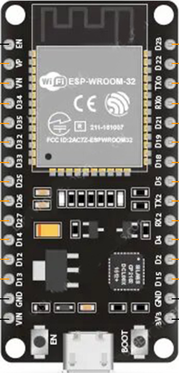
Pin Configuration and Descriptions

The ESP32 WROOM-32 module has 38 pins. Below is a table of the most commonly used pins and their functions:

Pin Number Pin Name Function Description
1 EN Enable pin (active high)
2 IO0 GPIO0, used for boot mode selection
3 IO1 (TX0) GPIO1, UART0 TX
4 IO3 (RX0) GPIO3, UART0 RX
5 IO4 GPIO4, general-purpose I/O
6 IO5 GPIO5, general-purpose I/O
7 IO12 GPIO12, ADC2 channel 5
8 IO13 GPIO13, ADC2 channel 4
9 IO14 GPIO14, ADC2 channel 6
10 IO15 GPIO15, ADC2 channel 3
11 IO16 GPIO16, general-purpose I/O
12 IO17 GPIO17, general-purpose I/O
13 GND Ground
14 3V3 3.3V power supply

For a complete pinout, refer to the official Espressif datasheet.

Usage Instructions

How to Use the ESP32 in a Circuit

  1. Power Supply: Provide a stable 3.3V power supply to the 3V3 pin. Ensure the current rating of the power source is sufficient (at least 500 mA).
  2. Boot Mode: To upload code, connect GPIO0 to GND and reset the module. After uploading, disconnect GPIO0 from GND.
  3. Connections: Use UART pins (TX0 and RX0) for serial communication with a computer or microcontroller. Connect GPIO pins as needed for peripherals like sensors, actuators, or displays.
  4. Programming: The ESP32 can be programmed using the Arduino IDE, Espressif's ESP-IDF, or other development environments.

Important Considerations and Best Practices

  • Use level shifters if interfacing with 5V logic devices, as the ESP32 operates at 3.3V logic levels.
  • Avoid using ADC2 channels when Wi-Fi is active, as they share resources.
  • Use decoupling capacitors near the power pins to reduce noise and ensure stable operation.
  • Ensure proper grounding to avoid signal interference.

Example Code for Arduino UNO

Below is an example of how to blink an LED connected to GPIO2 of the ESP32 using the Arduino IDE:

// Blink an LED connected to GPIO2 on the ESP32
// Ensure the LED's anode is connected to GPIO2 and cathode to GND

#define LED_PIN 2  // Define the GPIO pin for the LED

void setup() {
  pinMode(LED_PIN, OUTPUT);  // Set GPIO2 as an output pin
}

void loop() {
  digitalWrite(LED_PIN, HIGH);  // Turn the LED on
  delay(1000);                  // Wait for 1 second
  digitalWrite(LED_PIN, LOW);   // Turn the LED off
  delay(1000);                  // Wait for 1 second
}

Troubleshooting and FAQs

Common Issues and Solutions

  1. ESP32 Not Detected by Computer

    • Ensure the correct USB driver (e.g., CP210x or CH340) is installed.
    • Check the USB cable for data transfer capability (some cables are power-only).
  2. Code Upload Fails

    • Verify that GPIO0 is connected to GND during the upload process.
    • Check the selected board and COM port in the Arduino IDE.
  3. Wi-Fi Connection Issues

    • Ensure the correct SSID and password are used in the code.
    • Check for interference or weak signal strength.
  4. Overheating

    • Verify that the power supply voltage does not exceed 3.6V.
    • Ensure proper ventilation and avoid short circuits.

FAQs

Q: Can the ESP32 operate on 5V?
A: No, the ESP32 operates at 3.3V. Applying 5V to its pins can damage the module.

Q: How do I reset the ESP32?
A: Press the EN (enable) button on the module to reset it.

Q: Can I use the ESP32 with a 5V Arduino?
A: Yes, but you must use level shifters to convert 5V signals to 3.3V.

Q: How do I use Bluetooth on the ESP32?
A: The ESP32 supports both Bluetooth Classic and BLE. Use the Arduino IDE or ESP-IDF to configure and program Bluetooth functionality.

For more detailed information, refer to the official Espressif documentation.