
How to Use RGB LED: Examples, Pinouts, and Specs
 Design with RGB LED in Cirkit Designer
Introduction
The RGB LED, manufactured by Nichia (Part ID: RGB LED), is a versatile light-emitting diode capable of emitting red, green, and blue light. By adjusting the intensity of these three primary colors, the RGB LED can produce a wide spectrum of colors, making it an essential component in modern lighting and display technologies.
Explore Projects Built with RGB LED
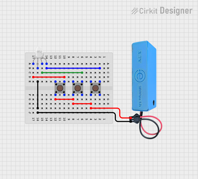 Open Project in Cirkit Designer
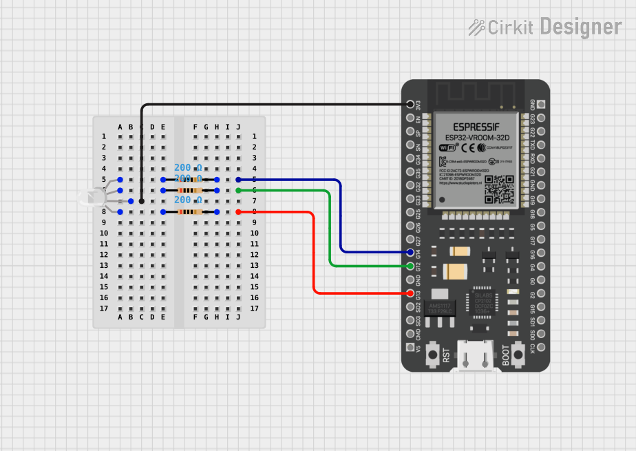 Open Project in Cirkit Designer
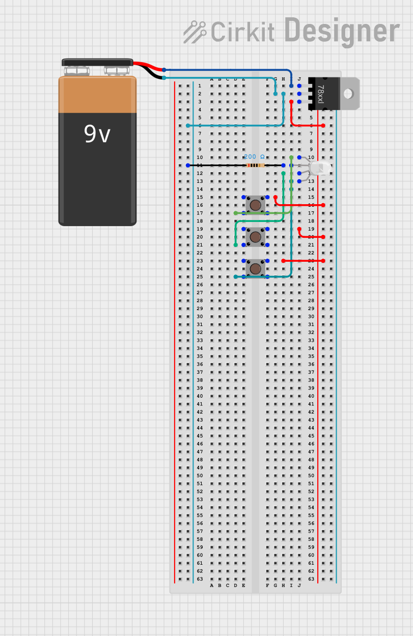 Open Project in Cirkit Designer
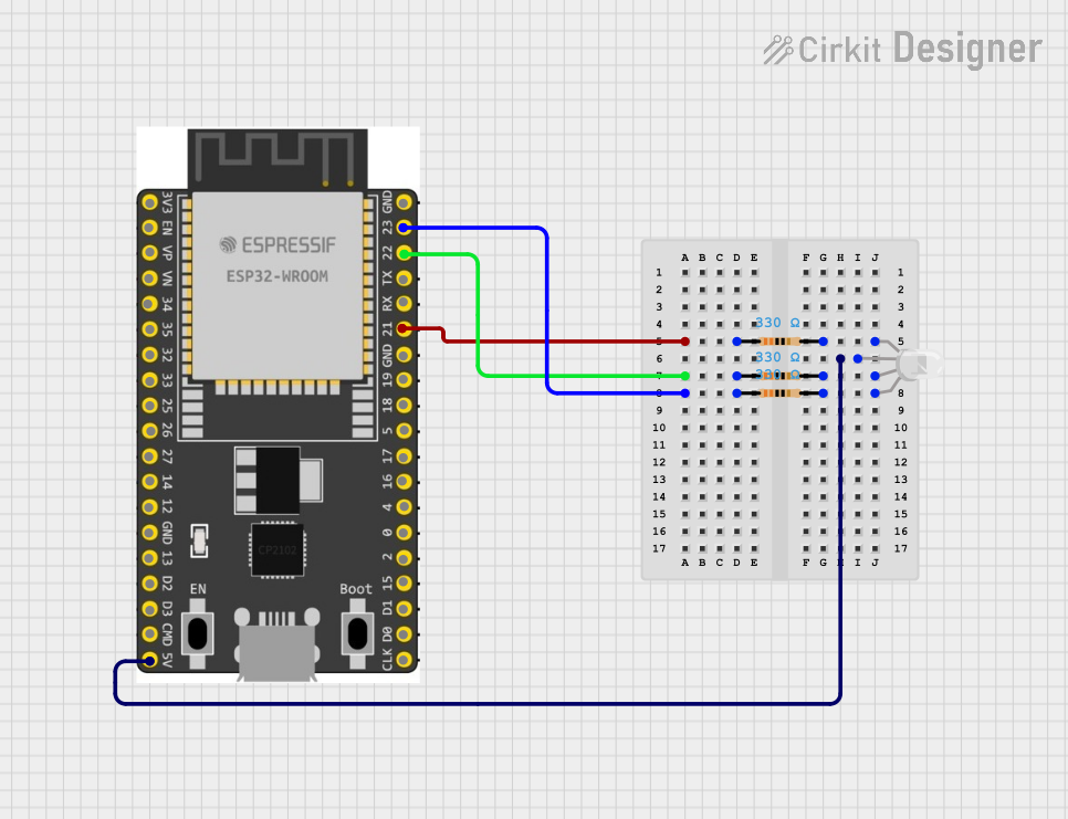 Open Project in Cirkit Designer
Explore Projects Built with RGB LED
Open Project in Cirkit DesignerOpen Project in Cirkit DesignerOpen Project in Cirkit DesignerOpen Project in Cirkit DesignerCommon Applications and Use Cases
- Decorative lighting and color-changing effects
- Status indicators in electronic devices
- Displays and signage
- DIY electronics and hobby projects
- Smart home lighting systems
Technical Specifications
Below are the key technical details for the Nichia RGB LED:
| Parameter | Value |
|---|---|
| Manufacturer | Nichia |
| Part ID | RGB LED |
| Forward Voltage (Red) | 2.0V - 2.4V |
| Forward Voltage (Green) | 3.0V - 3.4V |
| Forward Voltage (Blue) | 3.0V - 3.4V |
| Forward Current (typical) | 20mA per color channel |
| Maximum Current | 30mA per color channel |
| Wavelength (Red) | 620nm - 630nm |
| Wavelength (Green) | 515nm - 530nm |
| Wavelength (Blue) | 460nm - 475nm |
| Operating Temperature | -30°C to +85°C |
| Package Type | 4-pin or 6-pin (common cathode or anode) |
Pin Configuration
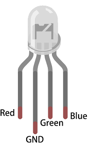
The RGB LED typically comes in a 4-pin configuration (common cathode or common anode). Below is the pinout description:
| Pin | Description |
|---|---|
| Pin 1 | Red LED Anode (R+) |
| Pin 2 | Common Cathode (or Anode) |
| Pin 3 | Green LED Anode (G+) |
| Pin 4 | Blue LED Anode (B+) |
Note: Ensure you verify whether your RGB LED is common cathode or common anode before connecting it to a circuit.
Usage Instructions
How to Use the RGB LED in a Circuit
- Determine the LED Type: Identify whether the RGB LED is common cathode or common anode.
- For common cathode: Connect the cathode pin to ground (GND).
- For common anode: Connect the anode pin to the positive voltage (Vcc).
- Use Current-Limiting Resistors: To prevent damage, connect a resistor in series with each color channel (Red, Green, Blue). Calculate the resistor value using Ohm's Law: [ R = \frac{V_{supply} - V_{forward}}{I_{forward}} ] Example: For a 5V supply and a red LED with a forward voltage of 2.2V and current of 20mA: [ R = \frac{5V - 2.2V}{0.02A} = 140\Omega ]
- Connect to a Microcontroller or Power Source: Use GPIO pins on a microcontroller (e.g., Arduino UNO) to control the RGB LED. Ensure the GPIO pins can handle the required current or use transistors if needed.
Arduino UNO Example Code
Below is an example of how to control an RGB LED using an Arduino UNO:
// Define RGB LED pins
const int redPin = 9;    // Red LED connected to PWM pin 9
const int greenPin = 10; // Green LED connected to PWM pin 10
const int bluePin = 11;  // Blue LED connected to PWM pin 11

void setup() {
  // Set RGB pins as output
  pinMode(redPin, OUTPUT);
  pinMode(greenPin, OUTPUT);
  pinMode(bluePin, OUTPUT);
}

void loop() {
  // Example: Cycle through colors
  setColor(255, 0, 0); // Red
  delay(1000);
  setColor(0, 255, 0); // Green
  delay(1000);
  setColor(0, 0, 255); // Blue
  delay(1000);
  setColor(255, 255, 0); // Yellow
  delay(1000);
  setColor(0, 255, 255); // Cyan
  delay(1000);
  setColor(255, 0, 255); // Magenta
  delay(1000);
  setColor(255, 255, 255); // White
  delay(1000);
}

// Function to set RGB LED color
void setColor(int redValue, int greenValue, int blueValue) {
  analogWrite(redPin, redValue);   // Set red intensity (0-255)
  analogWrite(greenPin, greenValue); // Set green intensity (0-255)
  analogWrite(bluePin, blueValue); // Set blue intensity (0-255)
}
Important Considerations and Best Practices
- Resistor Selection: Always use appropriate resistors to limit current and prevent damage to the LED.
- Heat Management: Avoid exceeding the maximum current rating to prevent overheating.
- PWM Control: Use Pulse Width Modulation (PWM) to control brightness and mix colors smoothly.
- Power Supply: Ensure the power supply voltage matches the LED's requirements.
Troubleshooting and FAQs
Common Issues and Solutions
LED Not Lighting Up
- Cause: Incorrect wiring or insufficient current.
- Solution: Double-check the connections and ensure resistors are correctly calculated.
Incorrect Colors Displayed
- Cause: Miswiring of the RGB pins.
- Solution: Verify the pin connections match the microcontroller's output.
LED Flickering
- Cause: Insufficient power supply or unstable PWM signals.
- Solution: Use a stable power source and ensure proper PWM frequency.
Overheating
- Cause: Excessive current through the LED.
- Solution: Use appropriate resistors and avoid exceeding the maximum current rating.
FAQs
Q: Can I use the RGB LED without a microcontroller?
A: Yes, you can use switches or potentiometers to manually control the color channels, but a microcontroller provides more precise control.
Q: How do I create custom colors?
A: Adjust the intensity of each color channel (Red, Green, Blue) using PWM signals to mix colors.
Q: What is the difference between common cathode and common anode RGB LEDs?
A: In a common cathode LED, all cathodes are connected to ground, while in a common anode LED, all anodes are connected to the positive voltage.
By following this documentation, you can effectively integrate the Nichia RGB LED into your projects and achieve stunning lighting effects!