
How to Use Adafruit ADS1115 16-Bit ADC: Examples, Pinouts, and Specs
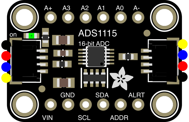
 Design with Adafruit ADS1115 16-Bit ADC in Cirkit Designer
Introduction
The Adafruit ADS1115 (Part ID: 1085) is a high-precision analog-to-digital converter (ADC) designed to provide 16-bit resolution for accurate measurement of analog signals. It features four single-ended or two differential input channels, making it ideal for interfacing with sensors, potentiometers, and other analog devices. The ADS1115 communicates via the I²C protocol, ensuring compatibility with a wide range of microcontrollers, including Arduino and Raspberry Pi.
Explore Projects Built with Adafruit ADS1115 16-Bit ADC
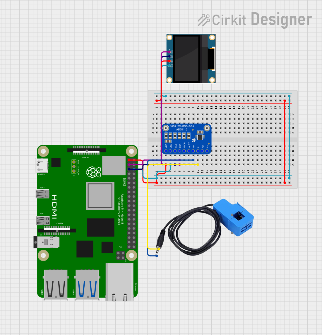 Open Project in Cirkit Designer
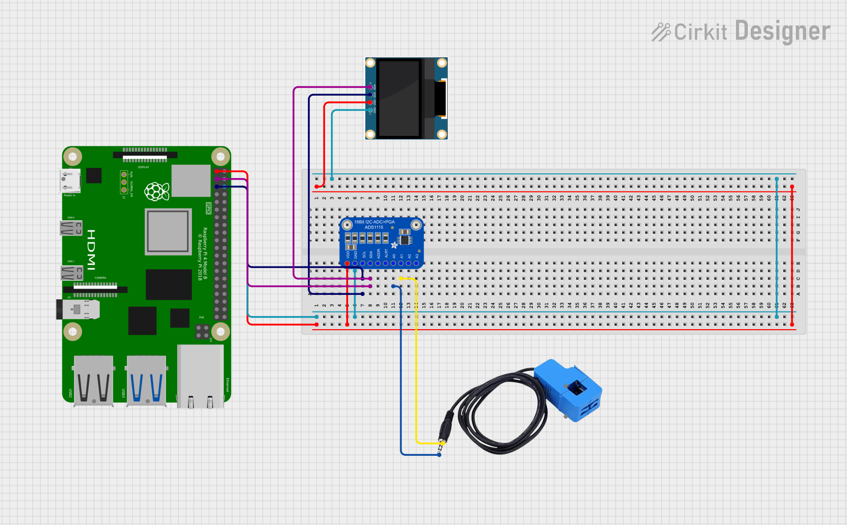 Open Project in Cirkit Designer
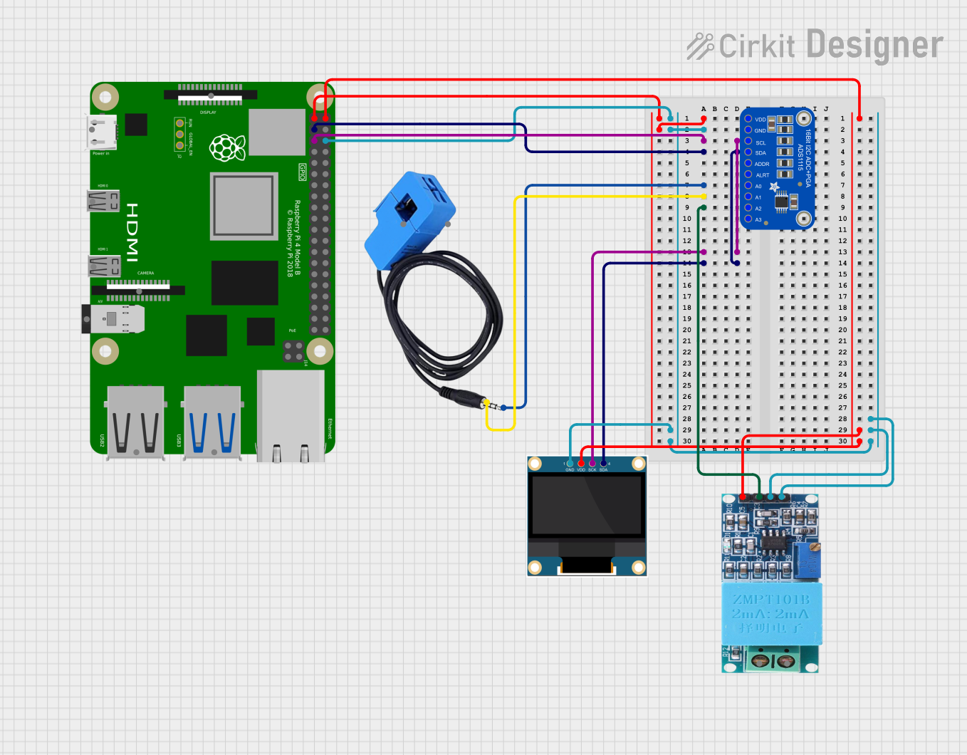 Open Project in Cirkit Designer
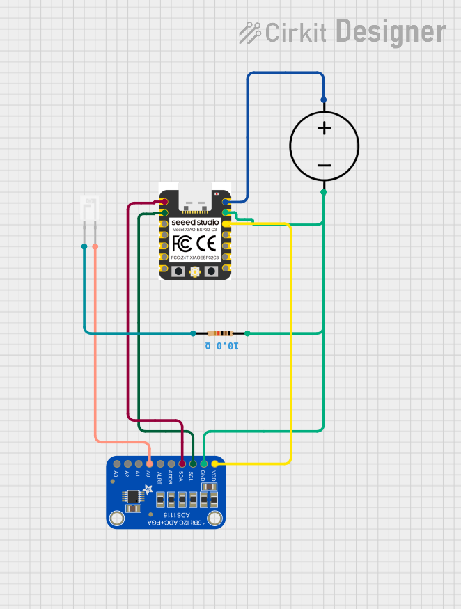 Open Project in Cirkit Designer
Explore Projects Built with Adafruit ADS1115 16-Bit ADC
Open Project in Cirkit DesignerOpen Project in Cirkit DesignerOpen Project in Cirkit DesignerOpen Project in Cirkit DesignerCommon Applications
- Sensor data acquisition (e.g., temperature, pressure, light sensors)
- Precision voltage measurement
- Battery monitoring
- Data logging systems
- Industrial control systems
Technical Specifications
The following table outlines the key technical details of the Adafruit ADS1115:
| Parameter | Value |
|---|---|
| Resolution | 16-bit |
| Input Channels | 4 single-ended or 2 differential |
| Input Voltage Range | 0 to VDD (single-ended), ±VDD (differential) |
| Programmable Gain Amplifier | 6 ranges (±0.256V to ±6.144V) |
| Supply Voltage (VDD) | 2.0V to 5.5V |
| Communication Interface | I²C (7-bit address: 0x48 by default) |
| Data Rate | Programmable: 8 SPS to 860 SPS |
| Operating Temperature | -40°C to +125°C |
| Current Consumption | 150 µA (typical) |
Pin Configuration
The ADS1115 has six pins, as described in the table below:
| Pin | Name | Description |
|---|---|---|
| 1 | VDD | Power supply input (2.0V to 5.5V). |
| 2 | GND | Ground connection. |
| 3 | SCL | I²C clock line. Connect to the microcontroller's SCL pin. |
| 4 | SDA | I²C data line. Connect to the microcontroller's SDA pin. |
| 5 | ADDR | Address pin. Sets the I²C address (0x48, 0x49, 0x4A, or 0x4B). |
| 6 | ALERT/RDY | Configurable as an alert pin or ready signal output. |
Usage Instructions
Connecting the ADS1115 to a Microcontroller
- Power Supply: Connect the VDD pin to a 3.3V or 5V power source, and the GND pin to ground.
- I²C Communication: Connect the SCL and SDA pins to the corresponding I²C pins on your microcontroller. Use pull-up resistors (typically 4.7kΩ) on the SCL and SDA lines if not already present.
- Address Configuration: Set the I²C address using the ADDR pin:
- Connect to GND for 0x48 (default).
- Connect to VDD for 0x49.
- Connect to SDA for 0x4A.
- Connect to SCL for 0x4B.
- Optional Alert Pin: If needed, connect the ALERT/RDY pin to a GPIO pin on your microcontroller for interrupt-based alerts.
Example Arduino Code
Below is an example of how to use the ADS1115 with an Arduino UNO to read a single-ended input:
#include <Wire.h>
#include <Adafruit_ADS1X15.h>

// Create an ADS1115 object
Adafruit_ADS1115 ads;

void setup() {
  Serial.begin(9600);
  // Initialize the ADS1115
  if (!ads.begin()) {
    Serial.println("Failed to initialize ADS1115!");
    while (1); // Halt execution if initialization fails
  }
  Serial.println("ADS1115 initialized.");
}

void loop() {
  // Read a single-ended input (channel 0)
  int16_t adcValue = ads.readADC_SingleEnded(0);

  // Convert the ADC value to voltage (assuming default gain ±6.144V)
  float voltage = adcValue * 0.1875 / 1000; // 0.1875 mV per bit

  // Print the voltage to the Serial Monitor
  Serial.print("Voltage: ");
  Serial.print(voltage);
  Serial.println(" V");

  delay(1000); // Wait 1 second before the next reading
}
Best Practices
- Use decoupling capacitors (e.g., 0.1µF) near the VDD pin to reduce noise.
- Ensure proper grounding to avoid measurement errors.
- Select the appropriate gain setting for your input voltage range to maximize resolution.
- Keep I²C lines as short as possible to minimize signal degradation.
Troubleshooting and FAQs
Common Issues
ADS1115 Not Detected on I²C Bus
- Solution: Verify the wiring of the SCL and SDA pins. Ensure pull-up resistors are present.
- Tip: Use an I²C scanner sketch to confirm the device address.
Incorrect Voltage Readings
- Solution: Check the gain setting and ensure the input voltage is within the selected range.
- Tip: Verify that the input signal is properly connected and not floating.
No Output on Serial Monitor
- Solution: Ensure the Serial Monitor baud rate matches the
Serial.begin()setting in the code. - Tip: Check for errors in the code or wiring.
- Solution: Ensure the Serial Monitor baud rate matches the
FAQs
Q: Can the ADS1115 measure negative voltages?
A: Yes, but only in differential mode. The voltage difference between the two inputs must remain within the selected gain range.
Q: What is the maximum sampling rate of the ADS1115?
A: The maximum sampling rate is 860 samples per second (SPS) when configured for the highest data rate.
Q: Can I use the ADS1115 with a 3.3V microcontroller?
A: Yes, the ADS1115 is compatible with both 3.3V and 5V systems.
Q: How do I use the ALERT/RDY pin?
A: The ALERT/RDY pin can be configured to trigger an interrupt when a conversion is complete or when a threshold is exceeded. Refer to the ADS1115 datasheet for configuration details.