How to Use 5A overcurrent protection module: Examples, Pinouts, and Specs
Introduction
The 5A Overcurrent Protection Module is a compact and reliable device designed to safeguard electrical circuits by interrupting the flow of current when it exceeds 5 amperes. This module prevents damage to sensitive components, reduces the risk of overheating, and ensures the safety of your electronic systems. It is widely used in power supply circuits, battery management systems, motor drivers, and other applications where current regulation is critical.
Explore Projects Built with 5A overcurrent protection module


Explore Projects Built with 5A overcurrent protection module
Common Applications and Use Cases
- Power Supply Protection: Prevents overcurrent damage in power distribution systems.
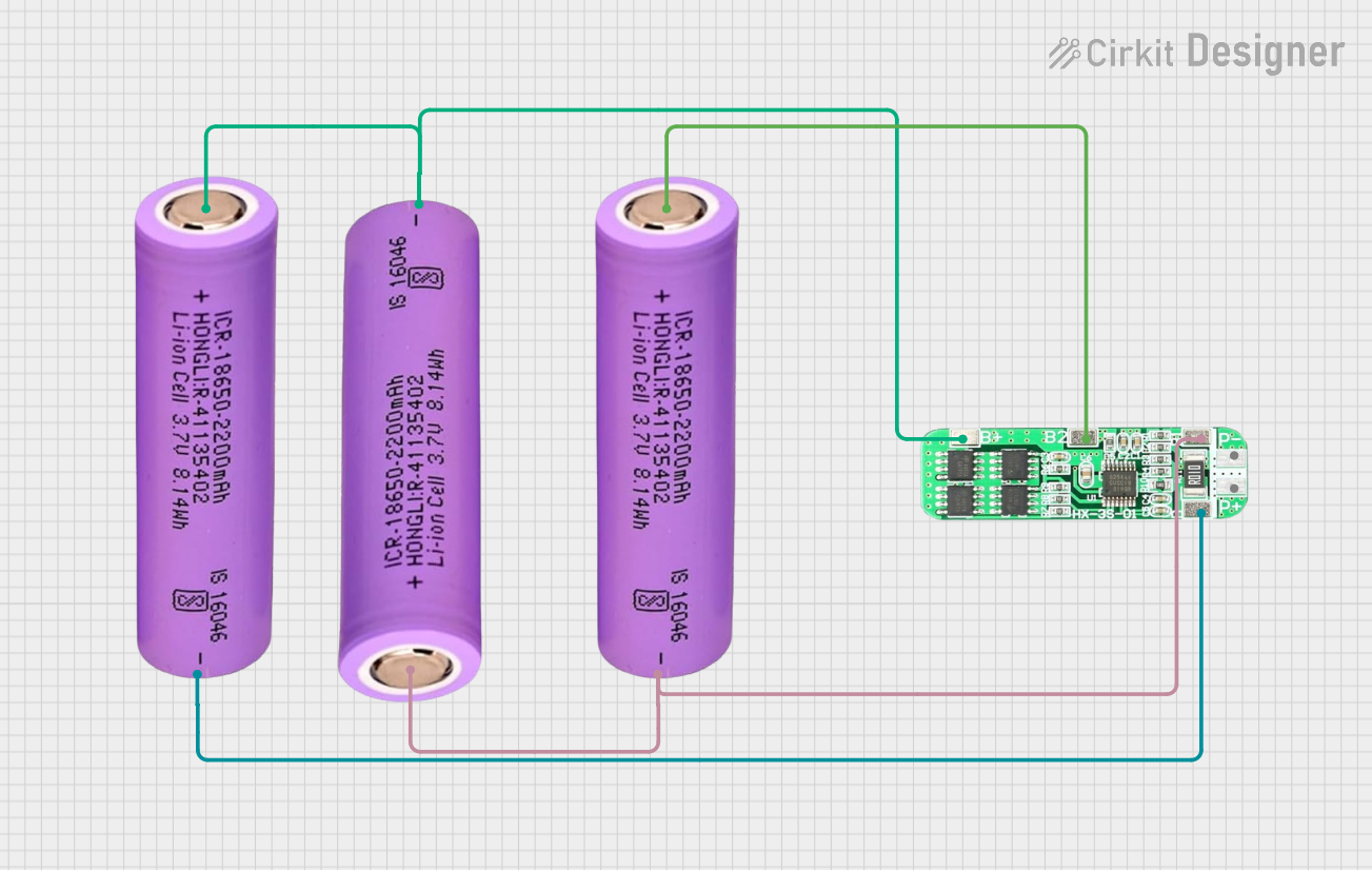
- Battery Management Systems: Protects batteries from excessive discharge or short circuits.
- Motor Drivers: Ensures safe operation of motors by limiting current surges.
- DIY Electronics Projects: Ideal for hobbyists working with high-current circuits.
- Industrial Equipment: Used in machinery to prevent electrical faults.
Technical Specifications
The following table outlines the key technical details of the 5A Overcurrent Protection Module:
| Parameter | Value |
|---|---|
| Operating Voltage | 5V to 36V |
| Maximum Current Rating | 5A |
| Trip Current Threshold | 5.5A ± 0.2A |
| Reset Type | Automatic or Manual (varies by model) |
| Response Time | < 1ms |
| Module Dimensions | 25mm x 15mm x 10mm |
| Operating Temperature | -40°C to 85°C |
Pin Configuration and Descriptions
The module typically has four pins or terminals. The table below describes each pin:
| Pin/Terminal | Label | Description |
|---|---|---|
| 1 | VIN | Input voltage terminal (connect to power source). |
| 2 | VOUT | Output voltage terminal (connect to load). |
| 3 | GND | Ground terminal (common ground for circuit). |
| 4 | RESET | Optional reset pin (manual reset for some models). |
Usage Instructions
How to Use the 5A Overcurrent Protection Module in a Circuit
- Connect the Power Source:
- Attach the positive terminal of your power source to the
VINpin. - Connect the negative terminal of your power source to the
GNDpin.
- Attach the positive terminal of your power source to the
- Connect the Load:
- Attach the positive terminal of your load to the
VOUTpin. - Ensure the load's negative terminal is connected to the common ground (
GND).
- Attach the positive terminal of your load to the
- Optional Reset Pin:
- If your module includes a
RESETpin, you can connect it to a push-button switch for manual reset functionality.
- If your module includes a
- Power On:
- Turn on the power source. The module will monitor the current and interrupt the circuit if the current exceeds 5A.
Important Considerations and Best Practices
- Current Rating: Ensure the load does not exceed the 5A limit under normal operating conditions.
- Heat Dissipation: The module may generate heat during operation. Use proper ventilation or a heatsink if necessary.
- Wiring: Use wires with appropriate gauge to handle the current without overheating.
- Reset Type: Check whether your module has an automatic or manual reset feature and use it accordingly.
- Testing: Before connecting sensitive components, test the module with a dummy load to verify its functionality.
Example: Using the Module with an Arduino UNO
The 5A Overcurrent Protection Module can be used to protect circuits powered by an Arduino UNO. Below is an example of how to integrate the module into a simple LED circuit:
Circuit Diagram
- Connect the Arduino's 5V pin to the
VINpin of the module. - Connect the
VOUTpin of the module to the positive terminal of the LED (with a current-limiting resistor in series). - Connect the LED's negative terminal to the Arduino's GND pin.
Sample Code
// Example code for controlling an LED with overcurrent protection
// Ensure the 5A Overcurrent Protection Module is connected between the Arduino
// and the LED circuit to prevent damage from excessive current.

const int ledPin = 9; // Pin connected to the LED

void setup() {
  pinMode(ledPin, OUTPUT); // Set the LED pin as an output
}

void loop() {
  digitalWrite(ledPin, HIGH); // Turn the LED on
  delay(1000);                // Wait for 1 second
  digitalWrite(ledPin, LOW);  // Turn the LED off
  delay(1000);                // Wait for 1 second
}
Troubleshooting and FAQs
Common Issues and Solutions
Module Does Not Trip at 5A:
- Cause: The load current may not have reached the trip threshold (5.5A ± 0.2A).
- Solution: Verify the load current using a multimeter and ensure it exceeds the trip threshold.
Module Trips Prematurely:
- Cause: Voltage spikes or transient currents may trigger the module.
- Solution: Add a capacitor (e.g., 100µF) across the
VINandGNDpins to filter out noise.
Module Overheats:
- Cause: Prolonged operation near the 5A limit or insufficient ventilation.
- Solution: Reduce the load current or improve heat dissipation with a heatsink.
Load Does Not Receive Power:
- Cause: Incorrect wiring or a tripped module.
- Solution: Double-check the wiring and reset the module if necessary.
FAQs
Q: Can the module handle currents above 5A for short durations?
A: The module is designed to trip at 5.5A ± 0.2A. Brief surges may be tolerated, but prolonged overcurrent will trigger the protection mechanism.Q: Is the module suitable for AC circuits?
A: No, this module is designed for DC circuits only. Using it in AC circuits may damage the module.Q: How do I know if the module has tripped?
A: The load will stop receiving power. Some models include an LED indicator to show the tripped state.Q: Can I adjust the trip current threshold?
A: No, the trip current is fixed at 5.5A ± 0.2A and cannot be adjusted.
This concludes the documentation for the 5A Overcurrent Protection Module. Follow the guidelines above to ensure safe and effective use of the module in your projects.