How to Use MPU6050 6DOF: Examples, Pinouts, and Specs
Introduction
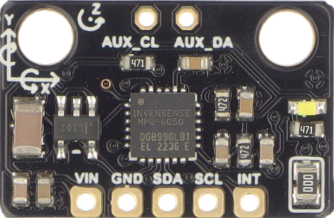
The MPU6050 is a 6 Degrees of Freedom (6DOF) inertial measurement unit (IMU) manufactured by DFRobot. It combines a 3-axis gyroscope and a 3-axis accelerometer, making it an essential component for applications requiring motion tracking and orientation sensing. This versatile sensor is widely used in robotics, drones, gaming devices, and wearable technology.
Explore Projects Built with MPU6050 6DOF
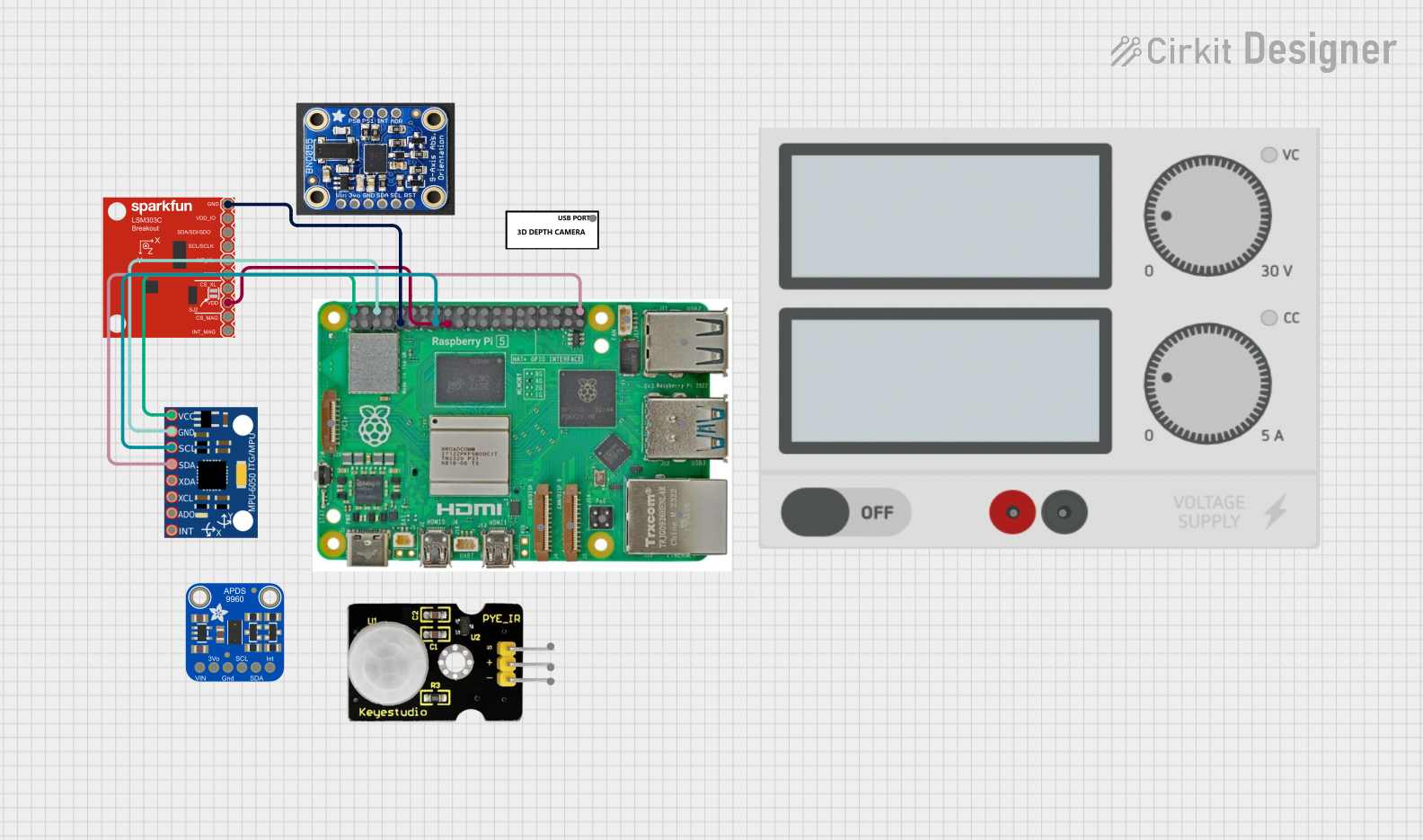
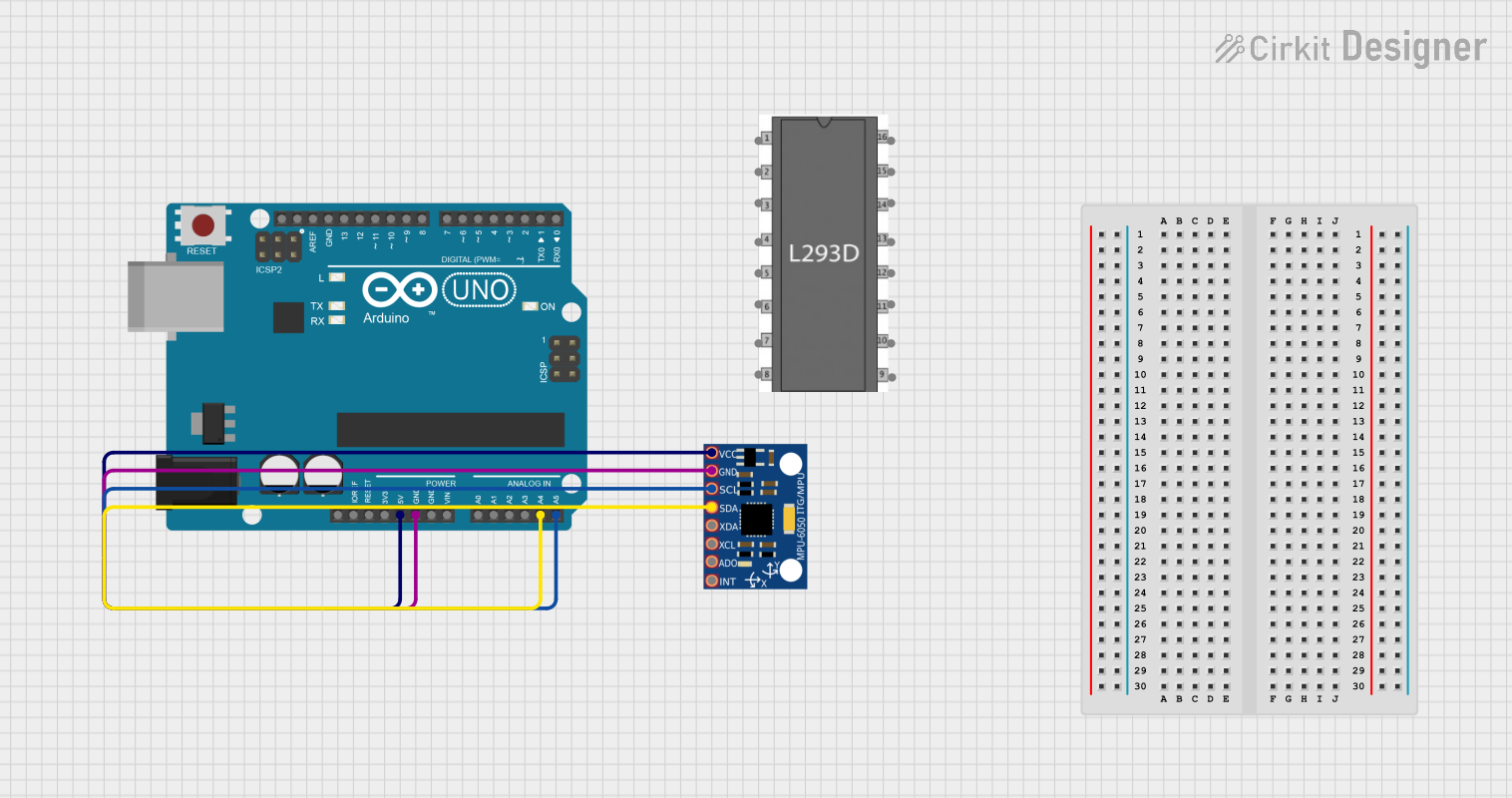
Explore Projects Built with MPU6050 6DOF
Technical Specifications
Key Technical Details
| Parameter | Value |
|---|---|
| Supply Voltage | 2.3V - 3.4V |
| Operating Current | 3.9mA (typical) |
| Gyroscope Range | ±250, ±500, ±1000, ±2000 °/s |
| Accelerometer Range | ±2g, ±4g, ±8g, ±16g |
| Communication | I2C (up to 400kHz) |
| Operating Temperature | -40°C to +85°C |
Pin Configuration and Descriptions
| Pin | Name | Description |
|---|---|---|
| 1 | VCC | Power supply (2.3V - 3.4V) |
| 2 | GND | Ground |
| 3 | SCL | I2C Clock Line |
| 4 | SDA | I2C Data Line |
| 5 | XDA | Auxiliary I2C Data Line (optional) |
| 6 | XCL | Auxiliary I2C Clock Line (optional) |
| 7 | AD0 | I2C Address Select (connect to GND for 0x68, |
| connect to VCC for 0x69) | ||
| 8 | INT | Interrupt (optional) |
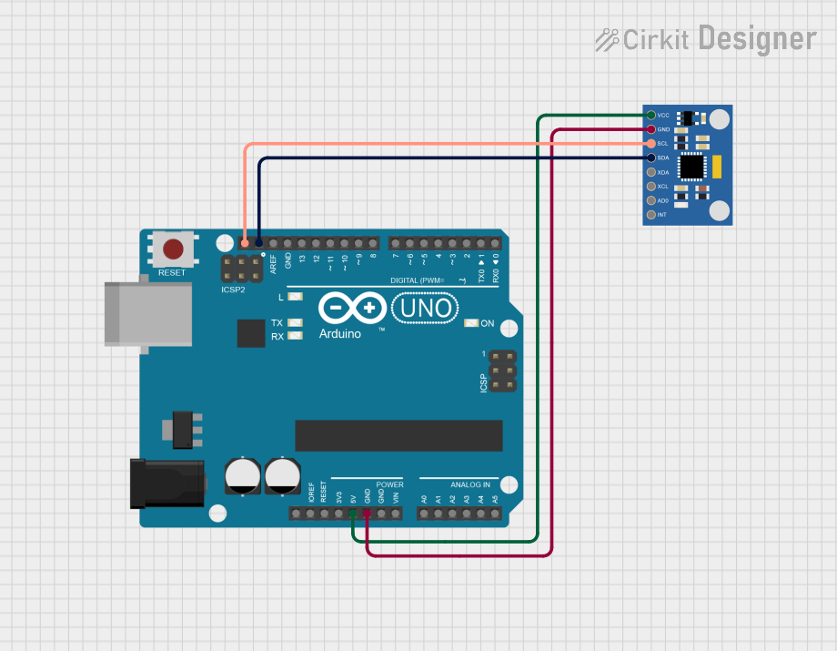
Usage Instructions
How to Use the MPU6050 in a Circuit
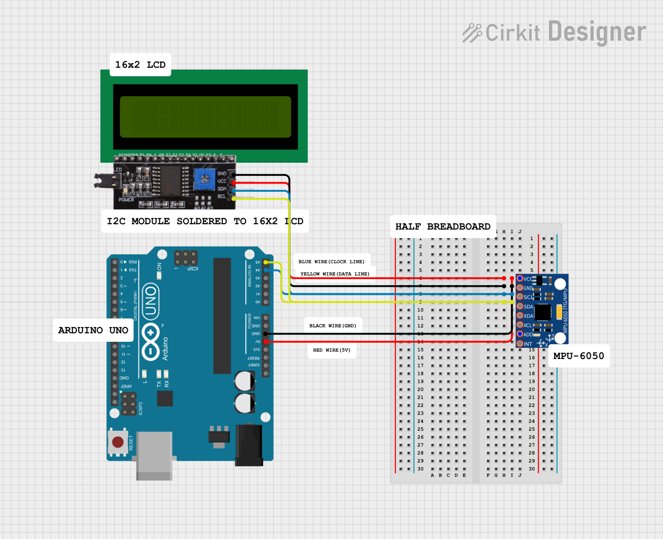
- Power Supply: Connect the VCC pin to a 3.3V power source and the GND pin to the ground.
- I2C Communication: Connect the SCL pin to the I2C clock line and the SDA pin to the I2C data line of your microcontroller.
- Address Selection: Connect the AD0 pin to GND for the default I2C address (0x68) or to VCC for the alternate address (0x69).
- Optional Connections: The XDA, XCL, and INT pins are optional and can be left unconnected if not used.
Important Considerations and Best Practices
- Power Supply: Ensure the power supply voltage is within the specified range (2.3V - 3.4V) to avoid damaging the sensor.
- I2C Pull-up Resistors: Use appropriate pull-up resistors (typically 4.7kΩ) on the SCL and SDA lines to ensure reliable I2C communication.
- Mounting Orientation: Mount the MPU6050 securely to minimize vibrations and ensure accurate measurements.
- Calibration: Perform calibration routines for both the gyroscope and accelerometer to improve accuracy.
Example Code for Arduino UNO
#include <Wire.h>
#include <MPU6050.h>

MPU6050 mpu;

void setup() {
  Wire.begin();
  Serial.begin(9600);

  // Initialize MPU6050
  Serial.println("Initializing MPU6050...");
  if (!mpu.begin(MPU6050_SCALE_2000DPS, MPU6050_RANGE_2G)) {
    Serial.println("Could not find a valid MPU6050 sensor, check wiring!");
    while (1);
  }

  // Calibrate gyroscope
  Serial.println("Calibrating gyroscope...");
  mpu.calibrateGyro();

  // Set threshold sensibility. Default 3.
  // If you don't want use threshold, comment this line or set 0.
  mpu.setThreshold(3);
}

void loop() {
  Vector rawAccel = mpu.readRawAccel();
  Vector normAccel = mpu.readNormalizeAccel();

  Serial.print(" Xraw = ");
  Serial.print(rawAccel.XAxis);
  Serial.print(" Yraw = ");
  Serial.print(rawAccel.YAxis);
  Serial.print(" Zraw = ");
  Serial.println(rawAccel.ZAxis);

  Serial.print(" Xnorm = ");
  Serial.print(normAccel.XAxis);
  Serial.print(" Ynorm = ");
  Serial.print(normAccel.YAxis);
  Serial.print(" Znorm = ");
  Serial.println(normAccel.ZAxis);

  delay(500);
}
Troubleshooting and FAQs
Common Issues
No Communication with MPU6050:
- Solution: Check the I2C connections and ensure the correct I2C address is used. Verify that pull-up resistors are present on the SCL and SDA lines.
Inaccurate Readings:
- Solution: Perform calibration routines for both the gyroscope and accelerometer. Ensure the sensor is securely mounted to minimize vibrations.
Sensor Not Detected:
- Solution: Verify the power supply voltage and connections. Ensure the AD0 pin is correctly set for the desired I2C address.
FAQs
Q: Can the MPU6050 be used with a 5V microcontroller?
- A: Yes, but you need to use a level shifter for the I2C lines to avoid damaging the sensor.
Q: How do I calibrate the MPU6050?
- A: Calibration routines can be implemented in software. Libraries like
MPU6050for Arduino often include calibration functions.
- A: Calibration routines can be implemented in software. Libraries like
Q: What is the maximum sampling rate of the MPU6050?
- A: The MPU6050 can sample data at up to 1kHz for both the gyroscope and accelerometer.
This documentation provides a comprehensive guide to using the MPU6050 6DOF IMU. Whether you are a beginner or an experienced user, following these instructions and best practices will help you effectively integrate this sensor into your projects.