How to Use Traffic Light module: Examples, Pinouts, and Specs
Introduction
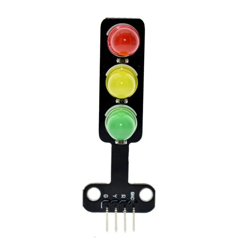
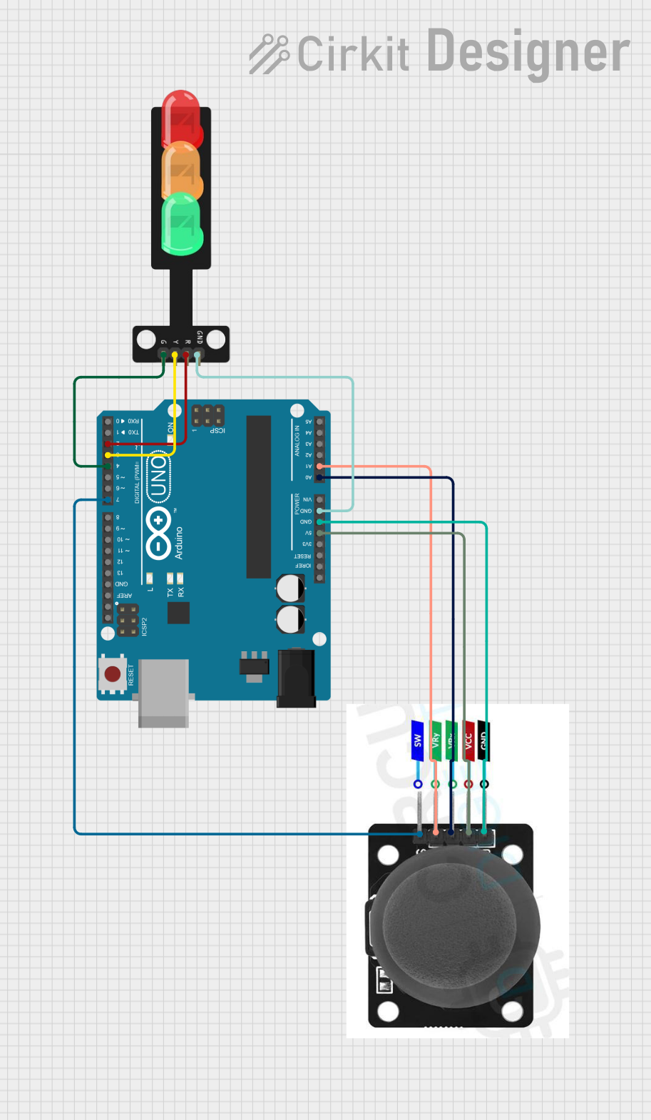
The Traffic Light Module by Sam (Part ID: Sam) is an electronic component designed to simulate the operation of real-world traffic lights. It features three LEDs—red, yellow, and green—arranged in a vertical layout to mimic standard traffic light behavior. This module is ideal for educational purposes, prototyping, and projects requiring traffic control simulation.
Explore Projects Built with Traffic Light module
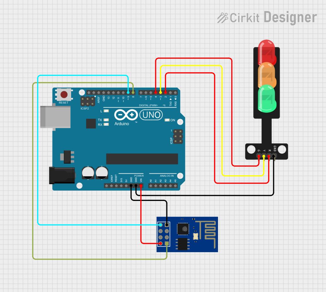
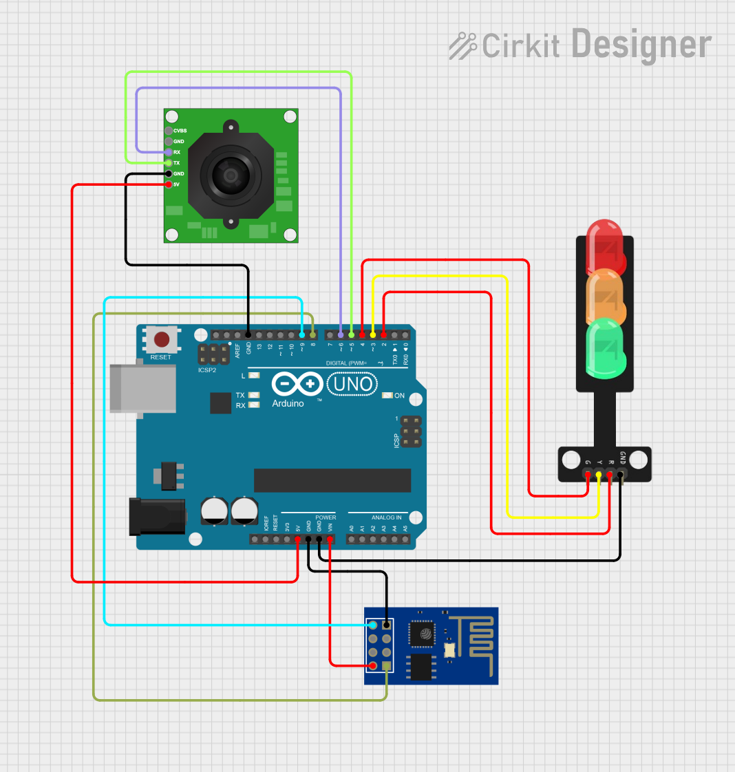
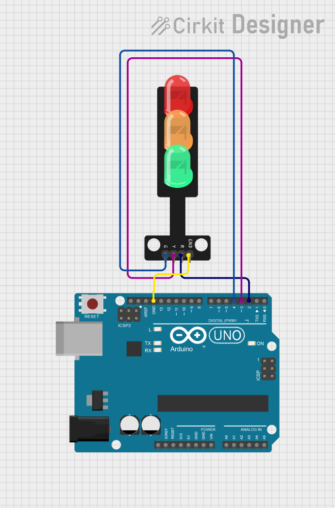
Explore Projects Built with Traffic Light module
Common Applications and Use Cases
- Educational demonstrations of traffic light systems
- Traffic flow simulation in model cities or robotics
- Arduino-based projects and microcontroller experiments
- Prototyping for smart traffic management systems
Technical Specifications
The following table outlines the key technical details of the Traffic Light Module:
| Parameter | Value |
|---|---|
| Operating Voltage | 3.3V - 5V |
| Current Consumption | ~20mA per LED (max) |
| LED Colors | Red, Yellow, Green |
| Dimensions | 30mm x 70mm x 10mm |
| Connector Type | 4-pin header (male) |
Pin Configuration and Descriptions
The module has a 4-pin header for easy interfacing. The pinout is as follows:
| Pin | Name | Description |
|---|---|---|
| 1 | GND | Ground connection |
| 2 | VCC | Power supply (3.3V - 5V) |
| 3 | Yellow | Control pin for the yellow LED |
| 4 | Green | Control pin for the green LED |
| 5 | Red | Control pin for the red LED |
Usage Instructions
How to Use the Component in a Circuit
- Power the Module: Connect the
VCCpin to a 3.3V or 5V power source and theGNDpin to ground. - Control the LEDs: Use a microcontroller (e.g., Arduino UNO) to control the
Red,Yellow, andGreenpins. Each pin can be connected to a digital output pin of the microcontroller. - Add Resistors (if needed): If the module does not include built-in resistors, connect a 220Ω resistor in series with each LED pin to limit current.
Important Considerations and Best Practices
- Voltage Compatibility: Ensure the module is powered within its operating voltage range (3.3V - 5V).
- Current Limiting: Verify whether the module has built-in resistors. If not, external resistors are required to prevent LED damage.
- Pin Connections: Double-check the pin connections to avoid short circuits or incorrect operation.
- Code Logic: Implement proper timing logic in your code to simulate realistic traffic light behavior.
Example Code for Arduino UNO
Below is an example Arduino sketch to control the Traffic Light Module:
// Pin definitions for the Traffic Light Module
const int redPin = 5;    // Connect the red LED pin to digital pin 5
const int yellowPin = 6; // Connect the yellow LED pin to digital pin 6
const int greenPin = 7;  // Connect the green LED pin to digital pin 7

void setup() {
  // Set the LED pins as outputs
  pinMode(redPin, OUTPUT);
  pinMode(yellowPin, OUTPUT);
  pinMode(greenPin, OUTPUT);
}

void loop() {
  // Simulate traffic light sequence

  // Turn on the red LED for 5 seconds
  digitalWrite(redPin, HIGH);
  digitalWrite(yellowPin, LOW);
  digitalWrite(greenPin, LOW);
  delay(5000); // Wait for 5 seconds

  // Turn on the yellow LED for 2 seconds
  digitalWrite(redPin, LOW);
  digitalWrite(yellowPin, HIGH);
  digitalWrite(greenPin, LOW);
  delay(2000); // Wait for 2 seconds

  // Turn on the green LED for 5 seconds
  digitalWrite(redPin, LOW);
  digitalWrite(yellowPin, LOW);
  digitalWrite(greenPin, HIGH);
  delay(5000); // Wait for 5 seconds
}
Troubleshooting and FAQs
Common Issues and Solutions
LEDs Not Lighting Up
- Cause: Incorrect wiring or insufficient power supply.
- Solution: Verify the connections and ensure the power supply is within the specified range (3.3V - 5V).
LEDs Are Dim
- Cause: High resistance in the circuit or low power supply voltage.
- Solution: Check for proper resistor values and ensure the power supply is stable.
Module Overheating
- Cause: Excessive current due to missing or incorrect resistors.
- Solution: Add appropriate resistors (e.g., 220Ω) in series with each LED pin.
Incorrect LED Behavior
- Cause: Faulty code logic or incorrect pin connections.
- Solution: Double-check the code and ensure the pins are connected as per the pinout table.
FAQs
Q: Can I use this module with a 12V power supply?
A: No, the module is designed for 3.3V to 5V operation. Using a 12V supply may damage the LEDs.
Q: Does the module include built-in resistors?
A: This depends on the specific version of the module. Check the manufacturer's datasheet or test the module to confirm.
Q: Can I control the module without a microcontroller?
A: Yes, you can use simple switches or a 555 timer circuit to control the LEDs manually.
Q: Is the module compatible with Raspberry Pi?
A: Yes, the module can be controlled by a Raspberry Pi, but ensure you use appropriate GPIO voltage levels (3.3V).
This concludes the documentation for the Traffic Light Module by Sam.