How to Use Transformer: Examples, Pinouts, and Specs
Introduction
A transformer is a passive electrical device that transfers electrical energy from one circuit to another through the process of electromagnetic induction. It consists of two or more coils of wire, known as windings, that are wound around a common core, typically made of laminated iron to minimize eddy current losses. Transformers are widely used in power distribution systems to step up (increase) or step down (decrease) voltage levels, in accordance with the needs of the application.
Explore Projects Built with Transformer


Explore Projects Built with Transformer
Common Applications and Use Cases
- Power Distribution: Stepping down high-voltage electricity from power stations to a lower voltage suitable for home and business use.
- Impedance Matching: Adjusting the impedance of a load to maximize power transfer or to limit current.
- Isolation: Electrically isolating different sections of a circuit for safety or noise reduction.
- Signal Coupling: Transferring signal from one circuit to another without direct electrical connection.
Technical Specifications
Key Technical Details
- Rated Power: The maximum power the transformer can handle without overheating, typically measured in VA (volt-amperes) or kVA (kilovolt-amperes).
- Primary Voltage: The voltage level at the input winding (primary winding).
- Secondary Voltage: The voltage level at the output winding (secondary winding).
- Frequency: The operating frequency range, usually 50/60 Hz for power transformers.
- Efficiency: The ratio of output power to input power, often expressed as a percentage.
- Isolation Voltage: The maximum voltage that can be applied between windings without breakdown.
Pin Configuration and Descriptions
| Pin Number | Description | Notes |
|---|---|---|
| P1 | Primary Winding Start | Connect to AC voltage source |
| P2 | Primary Winding End | |
| S1 | Secondary Winding Start | Output lower/higher AC voltage |
| S2 | Secondary Winding End |
Usage Instructions
How to Use the Transformer in a Circuit
- Identify Transformer Ratings: Ensure the transformer's power rating and voltage levels match your application requirements.
- Connect Primary Winding: Connect the primary winding (P1 and P2) to the AC voltage source. Observe proper polarity if specified.
- Connect Secondary Winding: Connect the secondary winding (S1 and S2) to the load. Again, observe polarity if necessary.
- Grounding: Properly ground the transformer core and any exposed metal to prevent shock hazards.
- Testing: Before applying full power, perform a test with a reduced voltage to ensure proper operation.
Important Considerations and Best Practices
- Overloading: Never exceed the rated power of the transformer to avoid overheating and potential failure.
- Cooling: Ensure adequate cooling for the transformer, especially for high-power applications.
- Mounting: Secure the transformer to prevent movement and reduce mechanical stress on the windings.
- Insulation: Maintain proper insulation between windings and between windings and the core to prevent shorts.
Troubleshooting and FAQs
Common Issues Users Might Face
- Overheating: Caused by overloading or poor ventilation. Check the load and ensure proper cooling.
- Humming Noise: Typically due to loose laminations or mountings. Tighten any loose parts.
- No Output Voltage: Check for proper connections, open circuit in windings, or a blown fuse.
Solutions and Tips for Troubleshooting
- Check Connections: Ensure all connections are secure and correct.
- Measure Input Voltage: Verify that the primary winding is receiving the correct voltage.
- Inspect for Physical Damage: Look for signs of damage to the windings or core.
- Use a Multimeter: Check for continuity in the windings and proper insulation resistance.
FAQs
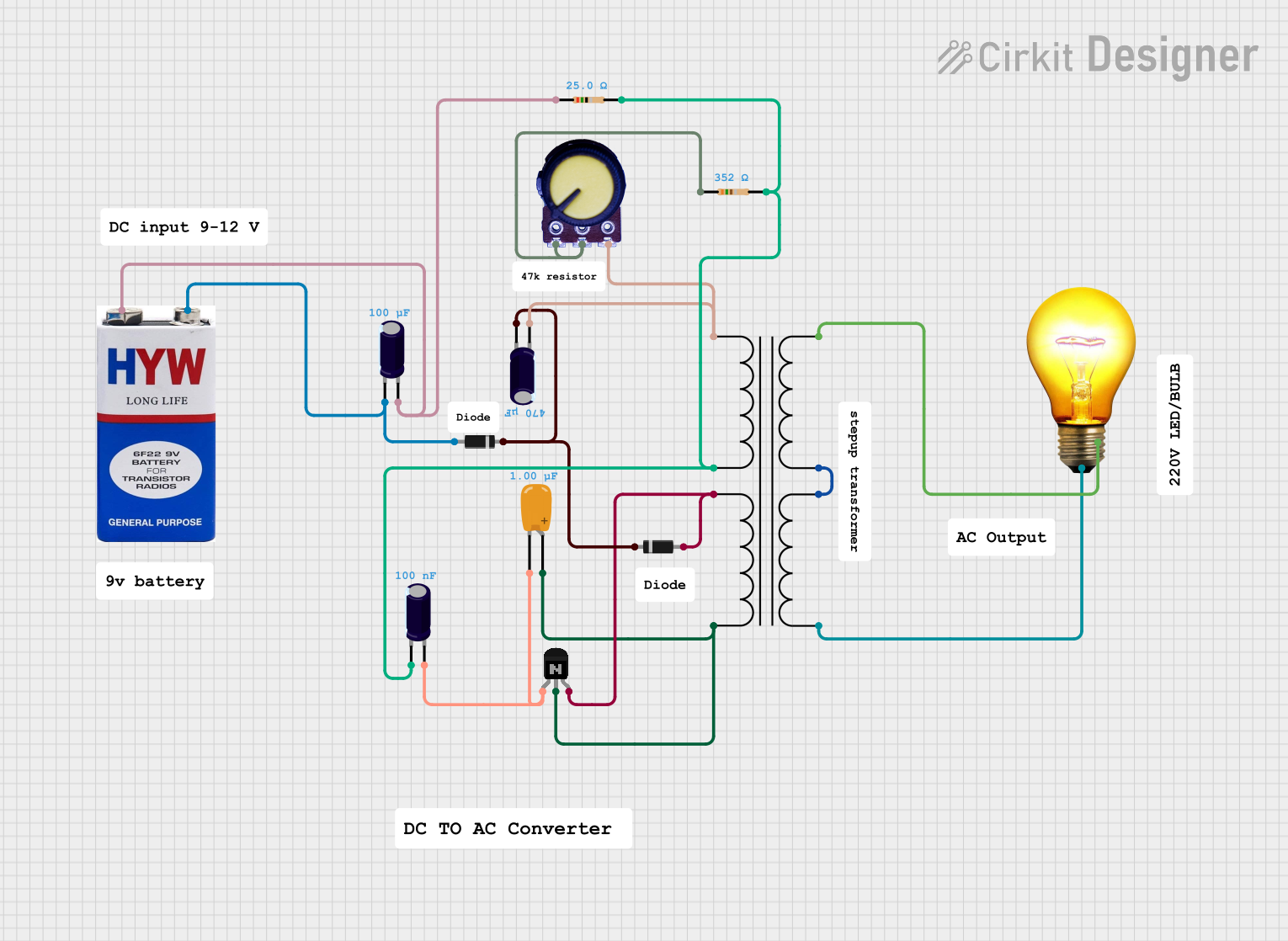
Q: Can I use a transformer to convert DC to AC? A: No, transformers only work with AC voltages due to the principle of electromagnetic induction.
Q: How do I know if my transformer is working properly? A: Measure the input and output voltages with a multimeter. The output should match the expected voltage based on the transformer's specifications.
Q: Can I adjust the output voltage of a transformer? A: Not directly. The output voltage is fixed based on the turns ratio. However, you can use a variable transformer (variac) for adjustable output.
Q: Is it safe to touch the secondary winding of a transformer? A: It can be safe if the transformer is designed for low-voltage output and is properly insulated and grounded. However, always exercise caution and follow safety guidelines.
Example Code for Arduino UNO
If you are using a transformer to power an Arduino UNO or to interface with it, ensure that the output voltage of the transformer is appropriate for the Arduino's voltage requirements. Here is an example of how to read an AC voltage using a transformer and Arduino:
// Example code to read AC voltage using Arduino UNO and a transformer
#include <Arduino.h>

const int analogInputPin = A0; // Connect to the secondary winding through a rectifier

void setup() {
  Serial.begin(9600);
}

void loop() {
  int sensorValue = analogRead(analogInputPin); // Read the analog value
  float voltage = sensorValue * (5.0 / 1023.0); // Convert to voltage
  Serial.print("AC Voltage: ");
  Serial.println(voltage);
  delay(1000); // Wait for a second before the next read
}
Note: This code assumes the use of a rectifier to convert the AC voltage to DC for the Arduino to read. The transformer's secondary voltage should be within the Arduino's input voltage range after rectification and regulation.
Remember to include proper voltage regulation and safety precautions when interfacing with the Arduino to prevent damage to the microcontroller.