The SW 3518 is a single-pole double-throw (SPDT) switch designed for controlling electrical circuits. This versatile switch allows users to toggle between two different circuits or states, making it an essential component in applications requiring manual control of power or signal routing. Its compact design and reliable performance make it suitable for a wide range of electronic and electrical projects.
Explore Projects Built with SW 3518
Use Cirkit Designer to design, explore, and prototype these projects online. Some projects support real-time simulation. Click "Open Project" to start designing instantly!
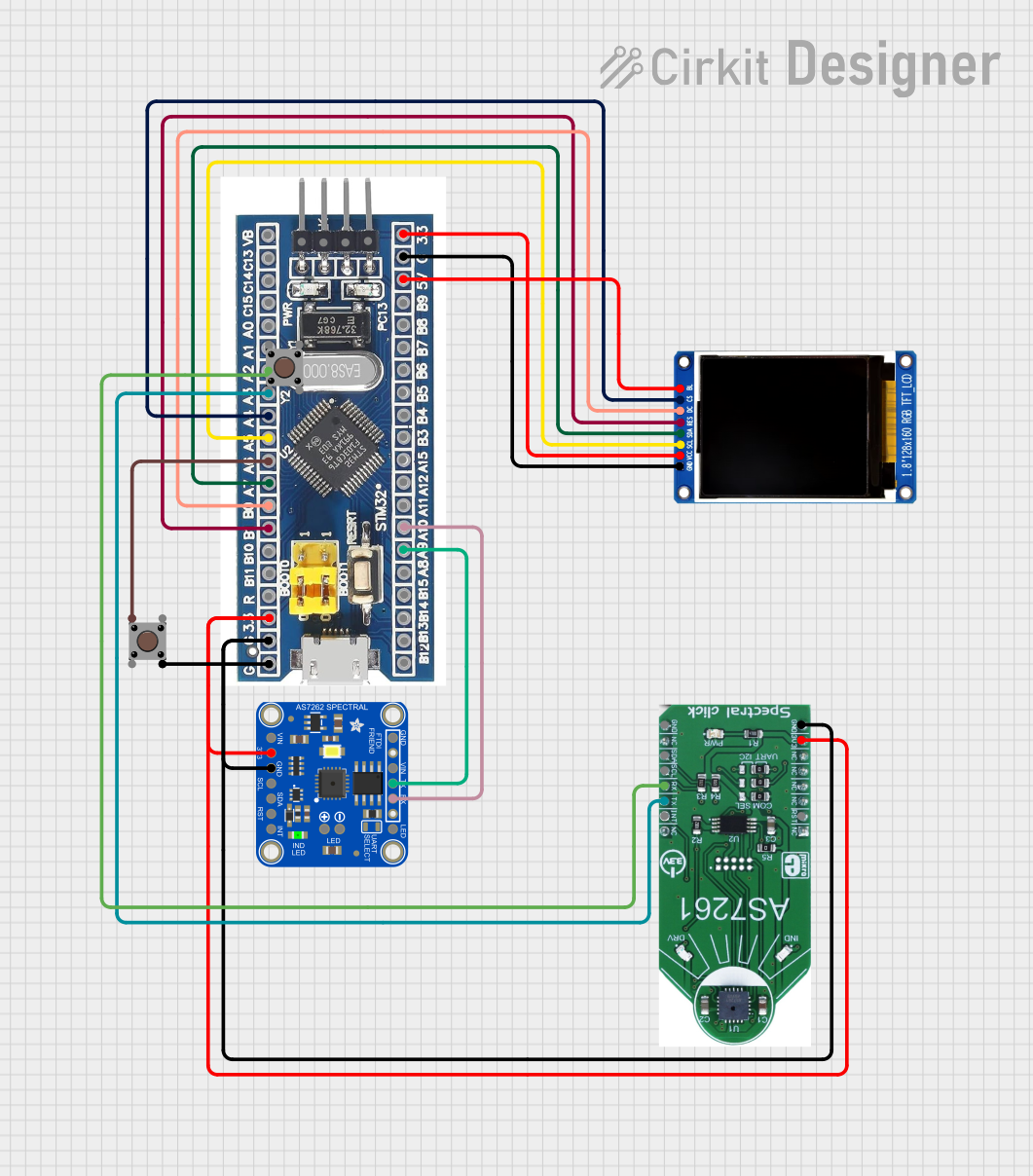
This circuit features an STM32F103C8T6 microcontroller interfaced with a China ST7735S 160x128 display and two spectral sensors (Adafruit AS7262 and AS7261). It also includes two pushbuttons for user input, with the microcontroller managing the display and sensor data processing.
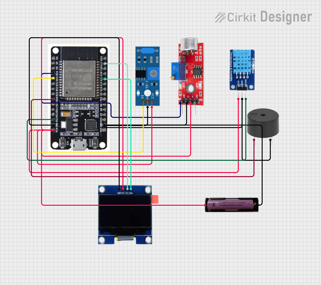
This circuit features an ESP32 microcontroller connected to various sensors and output devices. A sound sensor and a SW-420 vibration sensor provide analog and digital inputs, respectively, to the ESP32 for environmental monitoring. The circuit also includes a DHT11 sensor for temperature and humidity readings, a buzzer for audible alerts, and an OLED display for visual feedback, all interfaced with the ESP32. Power is supplied by a 3.7V source connected to all components requiring VCC.
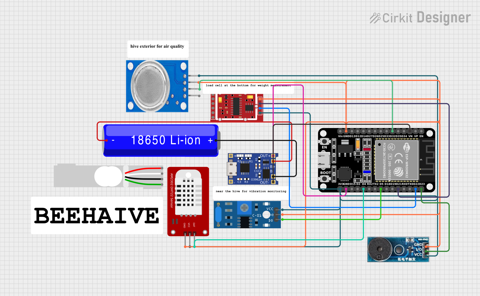
This circuit is a multi-sensor monitoring system powered by an ESP32 microcontroller. It includes sensors for gas (MQ135), vibration (SW-420), weight (HX711 with a load cell), and temperature/humidity (DHT22), along with a buzzer for alerts. The system is powered by a 18650 Li-ion battery managed by a TP4056 charging module.
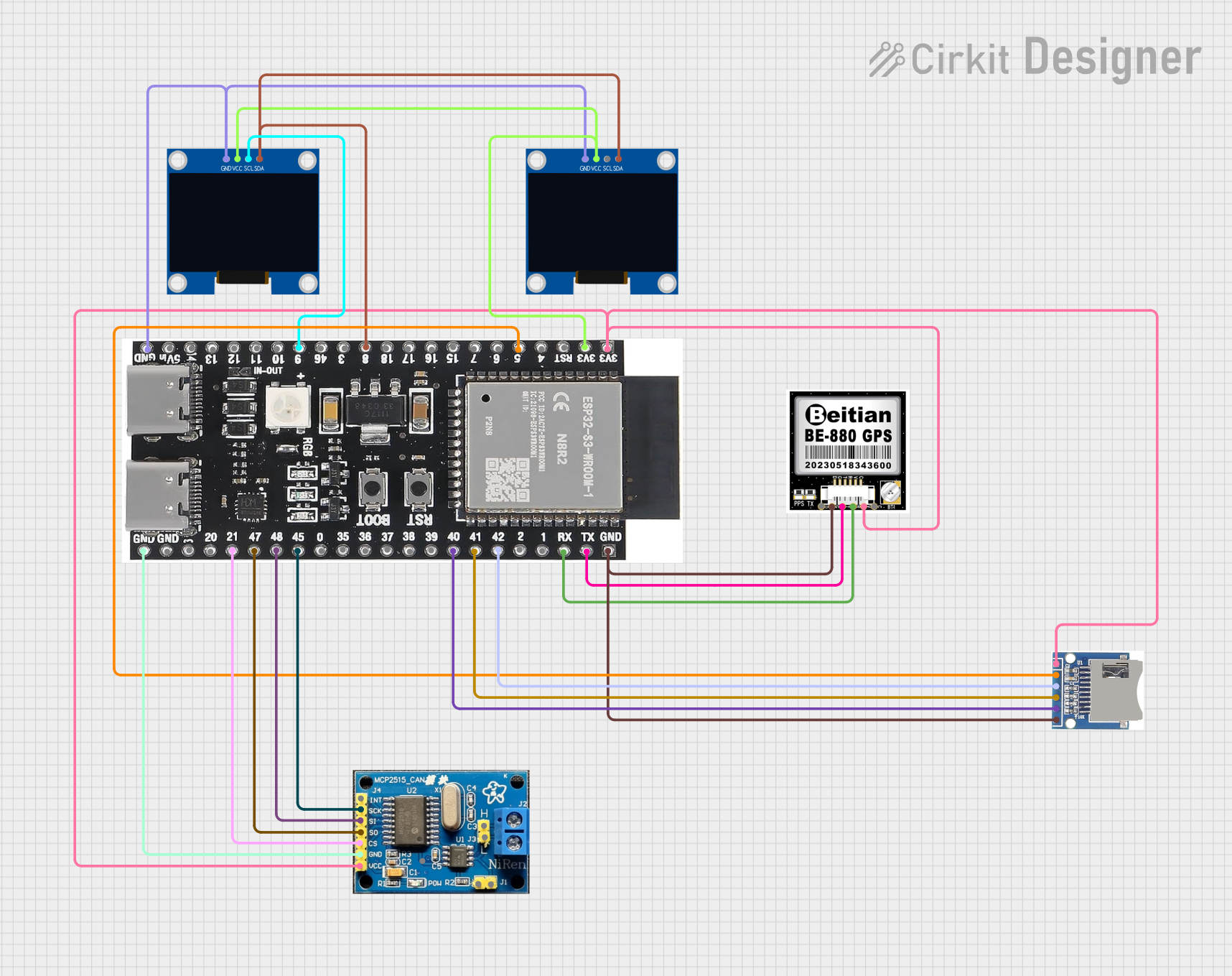
This circuit features an ESP32-S3 microcontroller interfaced with an SD card module, two OLED displays, a GPS module, and a CAN bus module. The ESP32-S3 records GPS data to the SD card, displays speed on one OLED, and shows wind speed from the CAN bus on the other OLED, providing a comprehensive data logging and display system.
The SW 3518 is a mechanical SPDT switch with the following key specifications:
Parameter
Value
Switch Type
Single-Pole Double-Throw (SPDT)
Operating Voltage
0–250V AC / 0–30V DC
Maximum Current
5A
Contact Resistance
≤ 50 mΩ
Insulation Resistance
≥ 100 MΩ
Mechanical Life
10,000 cycles
Operating Temperature
-20°C to +70°C
Dimensions
15mm x 10mm x 8mm
Mounting Type
Through-hole
Pin Configuration and Descriptions
The SW 3518 has three terminals, as described below:
Pin
Name
Description
1
Common (COM)
The central terminal that connects to either the Normally Open (NO) or Normally Closed (NC) terminal.
2
Normally Open (NO)
This terminal is disconnected from the COM terminal when the switch is in its default position. It connects to COM when the switch is toggled.
3
Normally Closed (NC)
This terminal is connected to the COM terminal when the switch is in its default position. It disconnects from COM when the switch is toggled.
Usage Instructions
How to Use the SW 3518 in a Circuit
Identify the Terminals: Locate the COM, NO, and NC terminals on the switch.
Connect the Circuit:
Connect the input signal or power source to the COM terminal.
Connect the first output (e.g., circuit A) to the NO terminal.
Connect the second output (e.g., circuit B) to the NC terminal.
Toggle the Switch: Flip the switch to route the signal or power between the NO and NC terminals.
Important Considerations and Best Practices
Voltage and Current Ratings: Ensure the voltage and current in your circuit do not exceed the switch's maximum ratings (250V AC / 30V DC, 5A).
Debouncing: When using the SW 3518 in digital circuits, consider implementing debouncing techniques to avoid false triggering caused by mechanical bounce.
Mounting: Secure the switch properly to prevent mechanical stress or damage during operation.
Environmental Conditions: Avoid exposing the switch to extreme temperatures, moisture, or corrosive environments to ensure long-term reliability.
Example: Connecting the SW 3518 to an Arduino UNO
The SW 3518 can be used as an input device for an Arduino UNO to toggle between two states. Below is an example circuit and code:
Circuit Diagram
Connect the COM terminal of the SW 3518 to Arduino pin 2.
Connect the NC terminal to GND.
Connect a pull-up resistor (10kΩ) between the COM terminal and 5V.
Arduino Code
// SW 3518 SPDT Switch Example with Arduino UNO
// This code reads the state of the switch and toggles an LED accordingly.

const int switchPin = 2;  // Pin connected to the COM terminal of the switch
const int ledPin = 13;    // Built-in LED pin on Arduino UNO

void setup() {
  pinMode(switchPin, INPUT_PULLUP); // Set switch pin as input with pull-up resistor
  pinMode(ledPin, OUTPUT);          // Set LED pin as output
}

void loop() {
  int switchState = digitalRead(switchPin); // Read the state of the switch

  if (switchState == LOW) {
    // Switch is toggled to NC (connected to GND)
    digitalWrite(ledPin, HIGH); // Turn on the LED
  } else {
    // Switch is toggled to NO (disconnected from GND)
    digitalWrite(ledPin, LOW);  // Turn off the LED
  }
}
Troubleshooting and FAQs
Common Issues and Solutions
Switch Not Working as Expected:
Cause: Incorrect wiring of the terminals.
Solution: Double-check the connections to the COM, NO, and NC terminals.
Intermittent Behavior in Digital Circuits:
Cause: Mechanical bounce in the switch.
Solution: Implement software or hardware debouncing techniques.
Switch Feels Stiff or Unresponsive:
Cause: Dirt or debris inside the switch mechanism.
Solution: Clean the switch carefully or replace it if necessary.
Overheating or Damage:
Cause: Exceeding the voltage or current ratings.
Solution: Ensure the circuit operates within the specified ratings of the switch.
FAQs
Q: Can the SW 3518 be used for DC circuits?
A: Yes, the SW 3518 supports DC circuits up to 30V and 5A.
Q: How do I implement debouncing in software?
A: You can use a delay or a state-change detection algorithm in your code to filter out false triggers caused by mechanical bounce.
Q: Is the SW 3518 suitable for high-frequency signal switching?
A: The SW 3518 is primarily designed for low-frequency applications. For high-frequency signals, consider using a relay or solid-state switch.
Q: Can I use the SW 3518 in outdoor environments?
A: The SW 3518 is not weatherproof. Use it in a protected enclosure if outdoor use is required.

 Open Project in Cirkit Designer