Cirkit Designer Logo
Cirkit Designer
Your all-in-one circuit design IDE
Home / 
Component Documentation

How to Use MT3608: Examples, Pinouts, and Specs

Image of MT3608
Cirkit Designer LogoDesign with MT3608 in Cirkit Designer

Introduction

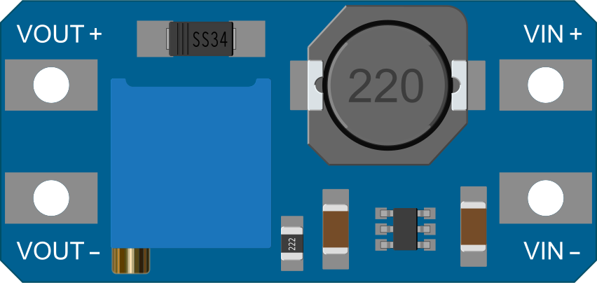
The MT3608 is a step-up (boost) voltage regulator module designed to provide a higher output voltage than the input voltage it receives. This component is widely used in battery-powered devices, portable electronics, and any application where voltage boosting is required to power electronics that operate at a higher voltage than the power source can provide.

Explore Projects Built with MT3608

Use Cirkit Designer to design, explore, and prototype these projects online. Some projects support real-time simulation. Click "Open Project" to start designing instantly!
ESP32-Controlled Bluetooth Robotic Vehicle with MT3608 Boost Converters and L298N Motor Drivers
Image of Copy of Diagrama Elétrico - AutoBots (1): A project utilizing MT3608 in a practical application
This circuit is designed to control multiple DC motors and a servo motor using an ESP32 microcontroller, which is interfaced with Bluetooth for wireless control commands. The ESP32 outputs control signals to two L298N motor drivers, which in turn drive the DC motors. The MT3608 modules are used to step up the voltage from a 4 x AAA battery mount to power the motor drivers, while the servo motor is directly controlled by the ESP32.
Cirkit Designer LogoOpen Project in Cirkit Designer
Voltage Regulation System with MT3608 Boost and LM2596 Buck Converters
Image of solar system router ups: A project utilizing MT3608 in a practical application
This circuit consists of two MT3608 boost converters and an LM2596 step-down module, each connected to separate 12V power supplies. The MT3608 modules are configured to step up the voltage from their respective power supplies, while the LM2596 module steps down the voltage from a 12V battery. Diodes are used to ensure correct current flow direction, potentially for protection or isolation between different parts of the circuit.
Cirkit Designer LogoOpen Project in Cirkit Designer
ESP32-Powered Obstacle Avoidance Robot with IR and Ultrasonic Sensors
Image of projcememek: A project utilizing MT3608 in a practical application
This circuit features a 18650 Li-Ion battery connected to a TP4056 charging module, which in turn is connected to an MT3608 boost converter to step up the voltage. The output of the MT3608 powers an ESP32 microcontroller, a TCRT 5000 IR sensor, an HC-SR04 ultrasonic sensor, and an MG996R servo motor. The ESP32 is configured to control the servo motor via GPIO 27 and to receive input signals from the IR sensor and ultrasonic sensor through GPIO 14 and GPIO 13, respectively.
Cirkit Designer LogoOpen Project in Cirkit Designer
ESP32-Controlled Traffic Light and DC Motors with MT3608 Boost Converters
Image of Diagrama Elétrico - AutoBots: A project utilizing MT3608 in a practical application
This circuit is designed to control a traffic light and multiple DC motors using an ESP32 microcontroller. The ESP32's GPIO pins are connected to the traffic light to control the green, yellow, and red LEDs, and to the L298N motor drivers for controlling the speed and direction of the DC motors. The MT3608 modules are used to step up the voltage from the AAA batteries to power the motor drivers, and the MG996R servo is controlled by the ESP32 for additional actuation tasks.
Cirkit Designer LogoOpen Project in Cirkit Designer

Explore Projects Built with MT3608

Use Cirkit Designer to design, explore, and prototype these projects online. Some projects support real-time simulation. Click "Open Project" to start designing instantly!
Image of Copy of Diagrama Elétrico - AutoBots (1): A project utilizing MT3608 in a practical application
ESP32-Controlled Bluetooth Robotic Vehicle with MT3608 Boost Converters and L298N Motor Drivers
This circuit is designed to control multiple DC motors and a servo motor using an ESP32 microcontroller, which is interfaced with Bluetooth for wireless control commands. The ESP32 outputs control signals to two L298N motor drivers, which in turn drive the DC motors. The MT3608 modules are used to step up the voltage from a 4 x AAA battery mount to power the motor drivers, while the servo motor is directly controlled by the ESP32.
Cirkit Designer LogoOpen Project in Cirkit Designer
Image of solar system router ups: A project utilizing MT3608 in a practical application
Voltage Regulation System with MT3608 Boost and LM2596 Buck Converters
This circuit consists of two MT3608 boost converters and an LM2596 step-down module, each connected to separate 12V power supplies. The MT3608 modules are configured to step up the voltage from their respective power supplies, while the LM2596 module steps down the voltage from a 12V battery. Diodes are used to ensure correct current flow direction, potentially for protection or isolation between different parts of the circuit.
Cirkit Designer LogoOpen Project in Cirkit Designer
Image of projcememek: A project utilizing MT3608 in a practical application
ESP32-Powered Obstacle Avoidance Robot with IR and Ultrasonic Sensors
This circuit features a 18650 Li-Ion battery connected to a TP4056 charging module, which in turn is connected to an MT3608 boost converter to step up the voltage. The output of the MT3608 powers an ESP32 microcontroller, a TCRT 5000 IR sensor, an HC-SR04 ultrasonic sensor, and an MG996R servo motor. The ESP32 is configured to control the servo motor via GPIO 27 and to receive input signals from the IR sensor and ultrasonic sensor through GPIO 14 and GPIO 13, respectively.
Cirkit Designer LogoOpen Project in Cirkit Designer
Image of Diagrama Elétrico - AutoBots: A project utilizing MT3608 in a practical application
ESP32-Controlled Traffic Light and DC Motors with MT3608 Boost Converters
This circuit is designed to control a traffic light and multiple DC motors using an ESP32 microcontroller. The ESP32's GPIO pins are connected to the traffic light to control the green, yellow, and red LEDs, and to the L298N motor drivers for controlling the speed and direction of the DC motors. The MT3608 modules are used to step up the voltage from the AAA batteries to power the motor drivers, and the MG996R servo is controlled by the ESP32 for additional actuation tasks.
Cirkit Designer LogoOpen Project in Cirkit Designer

Common Applications and Use Cases

  • Powering 5V or 12V devices from a lower voltage battery
  • Driving LED strings that require a higher operating voltage
  • Portable power supplies for electronic devices
  • Energy harvesting and solar-powered circuits

Technical Specifications

Key Technical Details

  • Input Voltage Range: 2V to 24V
  • Maximum Output Voltage: 28V (adjustable via onboard potentiometer)
  • Maximum Switch Current: 2A
  • Efficiency: Up to 93%
  • Switching Frequency: 1.2MHz
  • Built-in over-temperature protection

Pin Configuration and Descriptions

Pin Number Name Description
1 VIN Input voltage to the module (2V to 24V)
2 GND Ground reference for the module
3 VOUT Regulated output voltage (up to 28V)
4 GND Ground reference for the output

Usage Instructions

How to Use the MT3608 in a Circuit

  1. Connect the input voltage source to the VIN and GND pins.
  2. Connect the load to the VOUT and GND pins.
  3. Adjust the onboard potentiometer to set the desired output voltage. Use a multimeter to monitor the output voltage while adjusting.
  4. Ensure that the input voltage is at least 2V to start the boost conversion process.

Important Considerations and Best Practices

  • Do not exceed the maximum input voltage of 24V to prevent damage to the module.
  • The output voltage must be set higher than the input voltage for the module to operate correctly.
  • Avoid loading the module beyond its maximum switch current of 2A.
  • Provide adequate cooling if the module is expected to operate near its maximum ratings.
  • Keep the input and output wiring as short as possible to minimize losses and electromagnetic interference.

Troubleshooting and FAQs

Common Issues Users Might Face

  • Output voltage is lower than expected: Ensure that the input voltage is sufficient and the potentiometer is correctly adjusted.
  • Module is overheating: Check if the current draw is within the module's limits and improve cooling if necessary.
  • No output voltage: Verify connections and input voltage, and ensure the module is not damaged.

Solutions and Tips for Troubleshooting

  • If the output voltage cannot be adjusted, replace the potentiometer or the entire module if necessary.
  • In case of overheating, reduce the load or improve heat dissipation with a heatsink or better airflow.
  • For no output, double-check wiring and solder joints for any faults or loose connections.

Example Code for Arduino UNO

The MT3608 does not require any code to operate as it is not a programmable device. However, if you wish to monitor the output voltage using an Arduino UNO, you can use the following code to read the voltage through an analog input pin.

const int analogPin = A0; // Analog input pin connected to VOUT of MT3608
const float referenceVoltage = 5.0; // Reference voltage of Arduino UNO

void setup() {
  Serial.begin(9600);
}

void loop() {
  int sensorValue = analogRead(analogPin); // Read the analog value
  float voltage = sensorValue * (referenceVoltage / 1023.0); // Convert to voltage
  Serial.print("Output Voltage: ");
  Serial.println(voltage);
  delay(1000); // Wait for a second before reading again
}

Remember to use a voltage divider if the output voltage of the MT3608 is expected to exceed the reference voltage of the Arduino UNO to prevent damage to the microcontroller.