How to Use hall effect KY O35: Examples, Pinouts, and Specs
Introduction
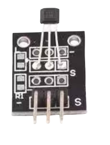
The Hall Effect KY-035 is a magnetic field sensor that detects the presence and strength of a magnetic field and converts it into an electrical signal. This sensor operates based on the Hall effect principle, where a voltage is generated perpendicular to the flow of current in the presence of a magnetic field. The KY-035 is widely used in applications such as position sensing, speed detection, proximity sensing, and current measurement. Its compact design and ease of use make it a popular choice for hobbyists and professionals alike.
Explore Projects Built with hall effect KY O35
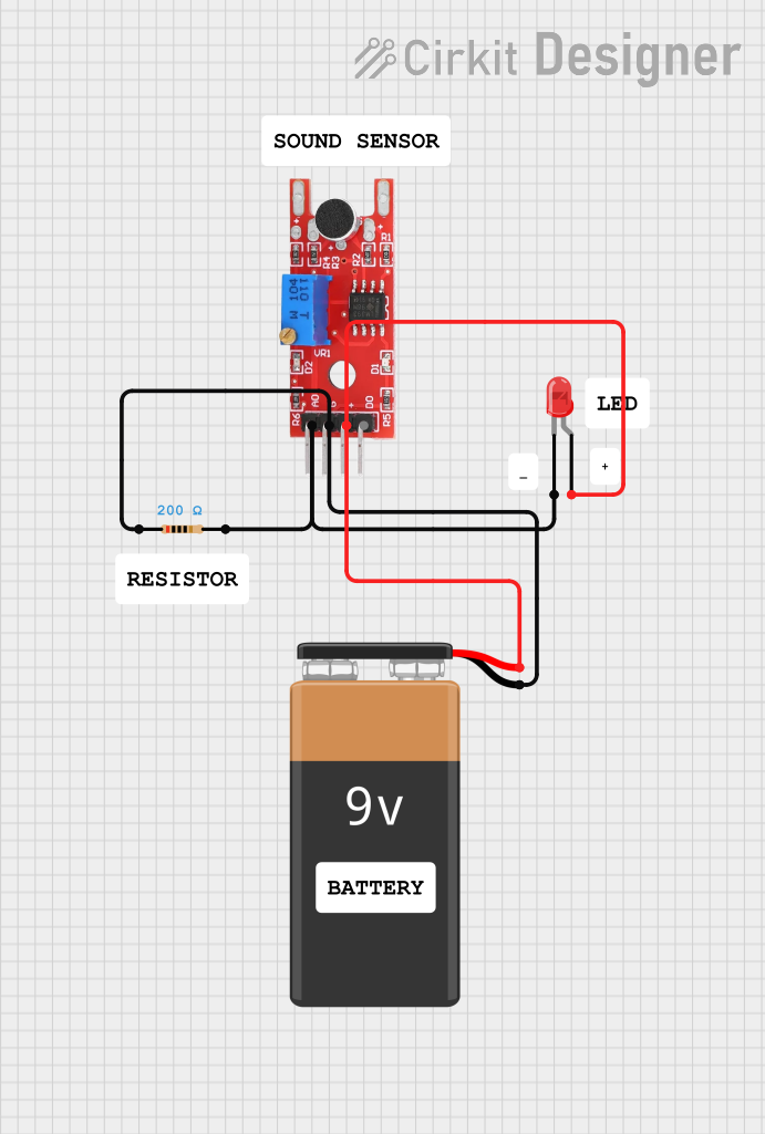
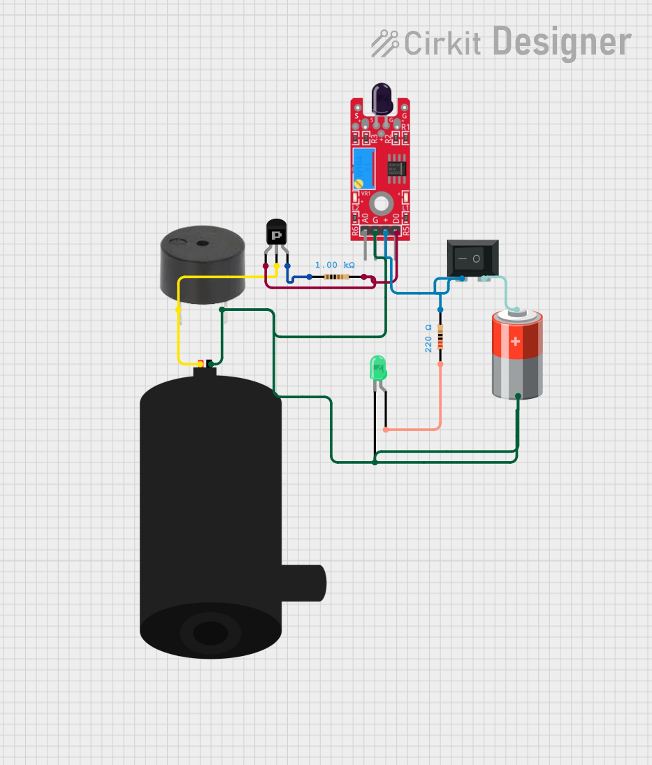

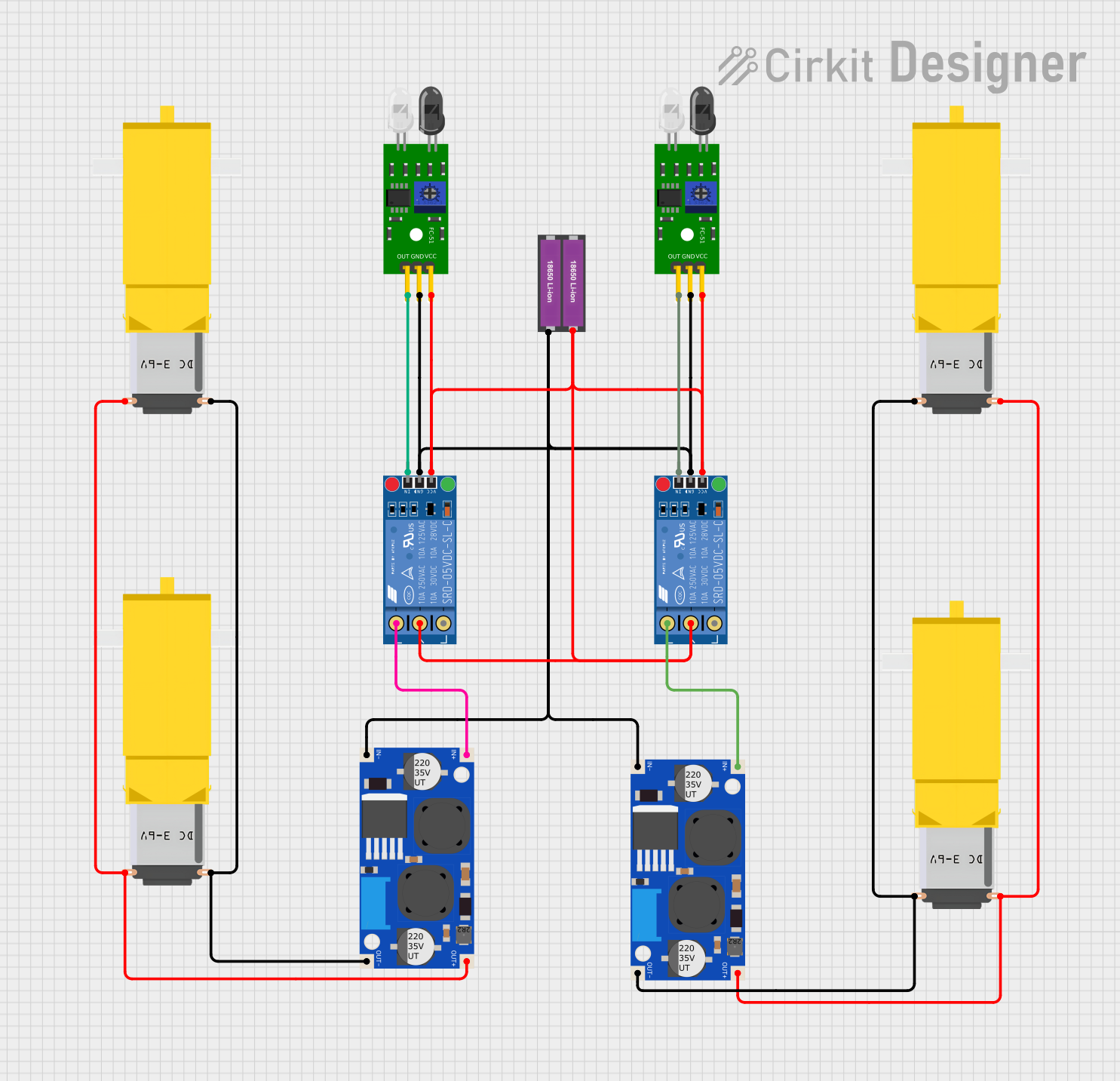
Explore Projects Built with hall effect KY O35
Technical Specifications
- Operating Voltage: 3.3V to 5V DC
- Output Type: Analog and Digital
- Sensitivity: Detects magnetic fields in the range of ±4mT to ±6mT
- Operating Temperature: -40°C to 85°C
- Dimensions: 32mm x 14mm x 7mm
Pin Configuration and Descriptions
The KY-035 has three pins, as detailed in the table below:
| Pin Number | Pin Name | Description |
|---|---|---|
| 1 | VCC | Power supply pin (3.3V to 5V DC) |
| 2 | GND | Ground pin |
| 3 | OUT | Output pin (Analog or Digital signal output) |
Usage Instructions
How to Use the KY-035 in a Circuit
- Power the Sensor: Connect the VCC pin to a 3.3V or 5V power source and the GND pin to the ground of your circuit.
- Connect the Output: The OUT pin provides the sensor's output. For analog readings, connect it to an analog input pin on your microcontroller. For digital readings, connect it to a digital input pin.
- Place the Sensor: Position the KY-035 near the magnetic field source. The sensor will detect the magnetic field's presence and strength.
- Read the Output: Monitor the output signal. A stronger magnetic field will result in a higher analog voltage or a digital HIGH signal.
Important Considerations and Best Practices
- Ensure the sensor is not exposed to magnetic fields beyond its detection range to avoid damage or inaccurate readings.
- Use pull-up or pull-down resistors if necessary when connecting the digital output to a microcontroller.
- Avoid placing the sensor near strong electromagnetic interference (EMI) sources, as this may affect its performance.
- For precise measurements, calibrate the sensor in your specific application environment.
Example Code for Arduino UNO
The following example demonstrates how to use the KY-035 with an Arduino UNO to read both analog and digital outputs:
// Define pin connections
const int analogPin = A0; // KY-035 analog output connected to A0
const int digitalPin = 2; // KY-035 digital output connected to D2

void setup() {
  Serial.begin(9600); // Initialize serial communication
  pinMode(digitalPin, INPUT); // Set digital pin as input
}

void loop() {
  // Read analog value from the sensor
  int analogValue = analogRead(analogPin);
  Serial.print("Analog Value: ");
  Serial.println(analogValue);

  // Read digital value from the sensor
  int digitalValue = digitalRead(digitalPin);
  Serial.print("Digital Value: ");
  Serial.println(digitalValue);

  // Add a small delay to avoid flooding the serial monitor
  delay(500);
}
Notes:
- The analog value will vary depending on the strength of the magnetic field.
- The digital output will be HIGH when the magnetic field exceeds a certain threshold.
Troubleshooting and FAQs
Common Issues and Solutions
No Output Signal
- Cause: Incorrect wiring or insufficient power supply.
- Solution: Double-check the connections and ensure the VCC pin is receiving 3.3V to 5V DC.
Inconsistent Readings
- Cause: Electromagnetic interference or unstable power supply.
- Solution: Place the sensor away from EMI sources and use a decoupling capacitor near the power pins.
Digital Output Always HIGH or LOW
- Cause: Magnetic field strength is outside the sensor's detection range.
- Solution: Verify the magnetic field strength and ensure it is within the sensor's range.
FAQs
Q: Can the KY-035 detect both north and south poles of a magnet?
A: Yes, the KY-035 can detect both poles of a magnet, but the output signal will vary depending on the pole's orientation and strength.
Q: Is the KY-035 suitable for high-speed applications?
A: The KY-035 is suitable for moderate-speed applications. For high-speed sensing, consider using a sensor with a faster response time.
Q: Can I use the KY-035 with a 3.3V microcontroller?
A: Yes, the KY-035 operates at both 3.3V and 5V, making it compatible with 3.3V microcontrollers like the ESP32 or Raspberry Pi Pico.
By following this documentation, you can effectively integrate the Hall Effect KY-035 sensor into your projects for reliable magnetic field detection.